
SCAN DUAL II - Scanner KONICA MINOLTA - Free user manual and instructions
Find the device manual for free SCAN DUAL II KONICA MINOLTA in PDF.

| Product Type | Film Scanner |
| Brand | Konica Minolta |
| Model | Scan Dual II |
| Scan Type | 35 mm film (slides and negatives) |
| Optical Resolution | 2820 dpi |
| Color Depth | 16 bits per channel |
| Light Source | LED |
| Scan Area | 24 x 36 mm |
| Connectivity | USB 2.0 |
| Power Supply | AC adapter |
| Dimensions | 165 x 72 x 35 mm |
| Weight | 300 g |
| Main Functions | Film scanning, color correction, dust removal |
| Maintenance and Cleaning | Clean optical elements with a soft, dry cloth; turn off before any maintenance. |
| Safety | Use only the supplied adapter; do not expose to moisture. |
| Spare parts and repairability | Not applicable, product is not user-repairable. |
| General Information | Manual available in PDF on notice-facile.com |
| Warranty | 2 years |
| Compatibility | Windows and Mac |
Frequently Asked Questions - SCAN DUAL II KONICA MINOLTA
User questions about SCAN DUAL II KONICA MINOLTA
0 question about this device. Answer the ones you know or ask your own.
Ask a new question about this device
Download the instructions for your Scanner in PDF format for free! Find your manual SCAN DUAL II - KONICA MINOLTA and take your electronic device back in hand. On this page are published all the documents necessary for the use of your device. SCAN DUAL II by KONICA MINOLTA.
USER MANUAL SCAN DUAL II KONICA MINOLTA
E 9224-2886-11 H-A006
MINLTA
Dimage Scan Dual II AF-2820U
©2000 Minolta Co., Ltd. All Right Reserved.
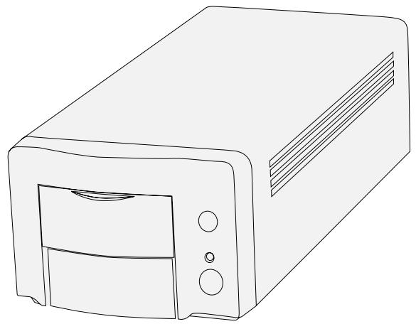
Thank you for purchasing the Minolta Dimâge Scan Dual2. The Dimâge Scan Dual2 AF-2820U is a dual format film scanner capable of scanning 35mm and, with the optional AD-10 APS Adapter, Advanced Photo System film.
This manual has been designed to help you understand the operation of your scanner. Please read this manual thoroughly to realize all the benefits of your scanner.
The instructions in this manual assume you have a working knowledge of the operating system for your computer (Macintosh OS, Windows 98, or Windows 2000) and its conventions. Familiarity with the mouse and standard operating system menus and commands is necessary before operating the driver software for the Dimâge Scan Dual2.
This manual does not instruct in the:
- basic use of personal computers.
- use of Windows 98, Windows 2000, or Macintosh OS.
- use of Adobe Photoshop, Paint Shop Pro, or Corel Draw.
The examples in this manual use Windows 98. The appearance of some screens may differ from the examples when using Windows 2000, or the Macintosh operating system.
Microsoft, Windows®, Windows 98®, and Windows 2000® are registered trademarks of the Microsoft Corporation.
Macintosh™, Apple®, and Power Macintosh® are registered trademarks of Apple Computer, Inc.
Adobe® and Photoshop™ are registered trademarks of Adobe Systems Incorporated.
Corel Draw™ is a trademark of the Corel Corporation.
Paint Shop Pro is the copyright of Met's Corporation.
Other corporate and product names are the trademarks and registered trademarks of their respective companies.
- Changes or modifications not approved by the party responsible for compliance could void the user's authority to operate the equipment.
- This manual may not be copied in part or whole without prior written permission from Minolta Co., Ltd. ©2000 Minolta Co., Ltd.
- Every necessary caution has been taken to ensure the accuracy of this instruction manual. Please contact us if you have any questions, find any errors, or notice missing information.
- Minolta is not responsible for loss, damage, or other results occurring during the operation of this product.

This mark certifies that this product meets the requirements of the EU (European Union) concerning interference causing equipment regulations. CE stands for Conformité Européenne.
Film Scanner:Dimage Scan Dual2 AF-2820U

Tested to comply with FCC standards.
FOR HOME OR OFFICE USE
This device complies with Part 15 of the FCC Rules. Operation is subject to the following conditions: (1) This device may not cause harmful interference, and (2) this device must accept any interference received, including interference that may cause undesired operation.
To meet FCC regulations, the SCSI cables used with this scanner must be equipped with ferrite cores.
This Class B digital apparatus complies with Canadian ICES-003.
Tested by the Minolta Corporation 101 Williams Drive Ramsey, New Jersey 07446 USA
Please read and understand each caution before using this product.

WARNING
To avoid fire or electric shock:
- Use only within the voltage range specified on the back of unit.
- Do not expose this unit to liquids.
- Do not insert metal objects into this unit.
- Do not touch the AC power adapter unit, cord or plug if your hands are wet.
- Unplug this unit when it is not in use.
Improper use of the AC power adapter cord may result in fire or electric shock.
- Insert the plug securely into an electrical outlet.
- Do not pull on the AC power adapter cord. Grasp the plug when removing the AC power adapter cord from an AC outlet (mains).
- Do not scratch, twist, modify, heat, or place a heavy object on the AC power adapter cord.
- Do not connect the ground to a gas pipe, telephone ground, or a water pipe. Improper grounding can result in electric shock.

This product must have sufficient ventilation while in use. Restricted ventilation ducts may cause the unit to overheat, increasing the risk of fire.
- Do not use or store this product in dusty or very humid areas.
- This product should be operated in the upright position only. Do not stack any objects on this product.
If there is smoke, a strange smell, or any other unusual conditions, shut down and unplug the unit, then contact a Minolta Service Facility.
Do not attempt to disassemble this product. It contains high-voltage circuits. Take the product to a Minolta Service facility for repairs.


CAUTION
Unexpected damage may occur if this unit is left unattended near young children.
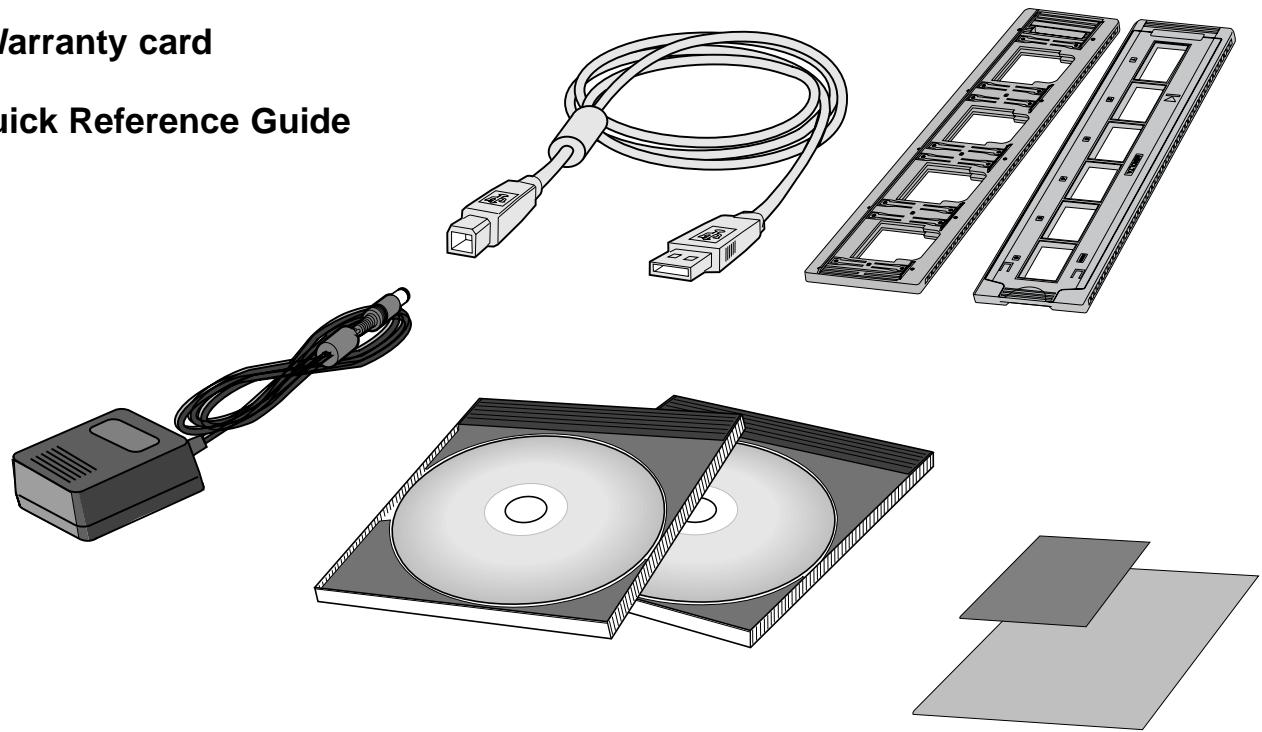
The following contents should be included in this package
- Minolta Dimâge Scan Dual2
- 35mm Slide holder (FH-U1) and Negative holder (SH-U1)
- USB cable
- AC power adapter (AC-U1, AC-U2 or AC-U3)
- CD ROM for DimAge Scan Dual II
- CD ROM for Photoshop LE
- Warranty card
- Quick Reference Guide
Software Registration
Please register this software before using it...
Once registered, you will receive technical support, software upgrade and product information. Complete and return the enclosed Product & Software Registration form after detaching it from the Warranty. No postage is necessary.
- The information you provide is confidential and will only be used by Minolta Customer Service and Product Research & Development.
The display indications may differ depending on your PC's preferences and a using version of the scanner driver.
Overview


This section describes the required system and the names of the parts.
Scanner setup


This section describes how to set up of the scanner.
Easy Scan Utility


This section describes how to load the film holder and perform the Minolta Easy Scan Utility.
Index Scan


This section describes how to perform the index scan.
Preview scan


This section describes how to perform the preview scan.
Image correction


This section describes how to perform the final scan and save it.
Final scan


Read this section if necessary.
Appendix

| FOR PROPER AND SAFE USE | .3 | |
| PACKAGE CONTENTS | .4 | |
| SCANNER - NAMES OF PARTS | .9 | |
| SYSTEM REQUIREMENTS - PC / AT | .10 | |
| SYSTEM REQUIREMENTS - MACINTOSH | .11 | |
| SCANNER | SCANNER SETUP FLOW | .13 |
| SETUP | INSTALLING THE PHOTSHOP LE - WINDOWS | .14 |
| INSTALLING THE PHOTOSHOP LE - MACINTOSH | .15 | |
| INSTALLING THE SOFTWARE - WINDOWS | .16 | |
| INSTALLING THE SOFTWARE - MACINTOSH | .19 | |
| CONNECTING THE HARDWARE | .21 | |
| EASY SCAN | EASY SCAN UTILITY FLOW | .23 |
| UTILITY | LAUNCHING Easy Scan Utility | .24 |
| WINDOWS 95/WINDOWS 2000 - Starting up the utility software | .24 | |
| MACINTOSH - Starting up the utility software | .24 | |
| Easy Scan Utility Window | .25 | |
| The Easy Scan Utility Window - Name of parts | .25 | |
| LOADING THE FILM HOLDER | .26 | |
| Loading the 35mm Negative Film Holder - FH-U1 | .26 | |
| Loading the Slide Mount Holder - SH-U1 | .27 | |
| APS ADAPTER (OPTIONAL) | .28 | |
| Names of Parts | .28 | |
| Loading the APS Adapter | .28 | |
| INSERTING THE FILM HOLDER INTO THE SCANNER | .29 | |
| Scanning with the FH-U1 35 mm film or SH-U1 slide film holder | .29 | |
| INSERTING THE APS ADAPTER | .30 | |
| SPECIFY THE FILM TYPE | .31 | |
| EASY INDEX SCAN | .32 | |
| Setting the usage | .32 | |
| Image Correction | .32 | |
| Rotate | .32 | |
| SPECIFY THE JOB TYPE/SAVING | .33 | |
| SCANNING FLOW | .35 | |
| LAUNCHING THE SOFTWARE | .36 | |
| Launching the TWAIN Driver - Windows | .36 | |
| Launching the Plug-in - Macintosh | .37 | |
| Launching the Utility Software | .38 | |
| MAIN WINDOW - Name of parts | .38 | |
| MAIN window | .38 | |
| The Command window part - Name of parts | .38 | |
| SETTING THE PREFERENCES | .39 | |
| SETTING THE FILM TYPE | .41 | |
| INDEX SCAN | INDEX SCAN - NAME OF PARTS | .42 |
| The Index tab part - Names of Parts | .42 | |
| INDEX SCAN | .43 | |
| Index scan | .43 | |
| Changing the Window Size | .43 | |
| SCANNING THE IMAGE | .44 | |
| Rotating the Index Frames | .45 | |
| Reversing Frame order | .45 | |
| SAVING INDEX SCAN IMAGE | .46 | |
| SAVING INDEX IMAGE FILE | .47 | |
| LOADING INDEX IMAGE FILE | .48 |
PREVIEW SCANNING FLOW 49
SCAN PRESCAN .50 The Prescan tab part - Names of parts .50
ORIENTING THE IMAGE 52
Rotate 52
Flip 53
Full screen view 54
Magnifying or Reducing the View 54
Scroll 55
AUTO-EXPOSURE LOCK 56
Setting AE-Lock 56
Cancelling AE-Lock 56
AE AREA LOCK 57
FOCUS-POINT AF 58
Focus 58
POINT AF 58
FOCUS-MANUAL 59
MANUAL FOCUS 59
CROPPING THE IMAGE 60
Auto Cropping 60
Cropping 60
PRESCAN AND IMAGE CORRECTION 61
APS formats; C, H and P (APS only) 62
RGB/CMY information 62
Displaying Frame number 62
E CORRECTION FLOW 63
IMAGE IMAGE CORRECTION FLOW 63
CORRECTION IMAGE CORRECTION 64
The Image Correction tab part - Names of parts .64
AUTOIMAGE CORRECTION 65
TONE CURVES/HISTOGRAM 66
The Tone Curves and Histogram Dialog Box - Names of Parts 66
Correcting the Tone Curves 67
Changing Tone Curves by Freehand 67
Correcting the Histogram 68
Setting the White or Black points 69
Viewing the Histogram of Images After Making Corrections 70
Auto Setting 70
Reset 70
BRIGHTNESS/CONTRAST/COLOR BALANCE 71
The Brightness, Contrast and
Color Balance Correction Dialog box - Names of parts 71
Auto Setting 72
Reset 73
The Hue, Saturation,
Lightness Correction Dialog box - Names of parts 73
Auto Setting 74
Reset 74
VARIATION CORRECTION 75
The Variation Dialog Box - Names of Parts 75
Selecting the Correction Item 75
Color Balance Correction 76
Brightness & Contrast Correction 76
Saturation Correction 77
Changing the Amount of Correction Step 77
Reset 77
SNAPSHOT 78
Storing in the Snapshot Display Area temporarily 78
Displaying the image stored temporarily as a prescan image 78
CANCELLING IMAGE CORRECTION 79
Cancelling the Image Correction 79
Redo the Correction 79
Delete the Image Correction 79
| FULL-SCREEN VIEW | .80 | |
| Full-Screen View | .80 | |
| Checking the Correction Result While Lining Up Images | .80 | |
| JOB SAVE/JOB LOAD | .81 | |
| Saving Image Correction Job | .81 | |
| Loading Image Correction Job | .82 | |
| FINAL SCAN | FLOW | .83 |
| SCAN SETTINGS | .84 | |
| The Scan Settings part window – Names of parts | .84 | |
| CREATING / DELETING JOB FILES | .87 | |
| Creating a Job | .87 | |
| Deleting a Job | .87 | |
| SCAN JOB TYPE | .88 | |
| FINAL SCAN | .89 | |
| Twain Driver / Plug-in Software | .89 | |
| Utility Software | .89 | |
| NAVIGATION | .90 | |
| The Navigation Dialog box – Name of parts | .90 | |
| Navigation Menu | .91 | |
| Saving, Selecting and Deleting a Navigation Setting | .92 | |
| APPENDIX A | APPENDIX | .93 |
| COLOR MATCHING | .94 | |
| Output color space setting | .95 | |
| ICC profile setting | .95 | |
| SCAN JOB FILE LIST – 35mm | .96 | |
| SCAN JOB FILE LIST – APS | .98 | |
| GLOSSARY | .99 | |
| TROUBLE SHOOTING | 101 | |
| SPECIFICATIONS | 102 | |
| USER TECHNICAL SUPPORT | 103 | |
| APPENDIX B | SOFTWARE-INSTALLATION – WINDOWS | |
| When the “Add New Hardware Wizard” window is displayed | .104 | |
| When the PC does not recognize the Dimâge Scan Dual II | .104 | |
| When the Dimâge Scan Dual II driver software does not start up | .106 | |
| WINDOWS 2000 | .108 | |
| CONTACTING MINOLTA | .108 |
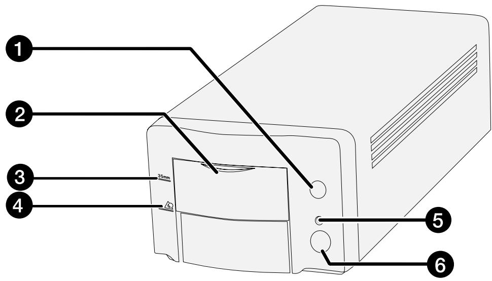
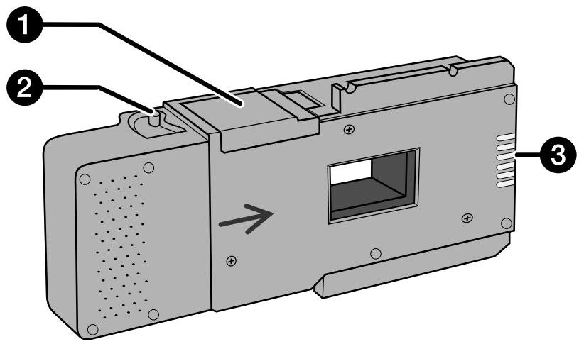
- Eject button
- Front door
- Mark of 35 mm Film
-
Mark of APS cassette
-
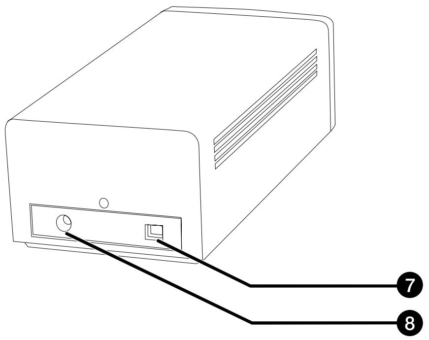
Indicator lamp
- Power switch
- USB port
- DC power input plug
| CPU: | IBM PC/AT compatible with an Intel Pentium or later processor or better. An Intel Pentium or later when Windows 98 or Windows 2000 is installed. • Support cannot be provided for custom or home built machines. |
Operating System: Windows 98, or Windows 2000 Professional.
Memory: A minimum of 32 MB RAM.
Hard Disk Space: 90 MB of available hard disk space.
Interface: USB Port
Monitor: XGA (1024 x 768) or better. VGA (640 x 480) can be used.
Other: TWAIN driver is compatible with Photoshop Ver.3.05, Ver.4.0.1, Ver.5.0.2, and Ver.5.5. Photoshop LE Paint Shop Pro 5.01, Corel Photo Paint 8.
CPU: Power PC
Operating System: Mac OS 8.5 - 9
Memory: A minimum of 16 MB application RAM in addition to the requirements for the Mac OS and Adobe Photoshop™
Hard Disk Space: 90 MB of available hard disk space.
Monitor: 19 inch (1024 x 768) monitor or better.
13 inch (640 x 480) monitor capable of displaying 32,000 colors.
Interface: USB port
Other: Plug-in is compatible with Photoshop Ver. 3.05, Ver. 4.01, Ver. 5.02 and Ver. 5.5. Photoshop LE
SCANNER SETUP
SCANNER SETUP FLOW
INSTALLING THE PHOTOSHOP LE
CONNECTING THE HARDWARE
INSTALLING THE SOFTWARE
GETTING STARTED

CAUTION – Before installing
- Please remove or disable any antivirus system extensions before launching this installer. These extensions may conflict with the operation of the installer. Replace or re-enable them when the installation is complete.
This manual describes how to install Adobe Photoshop LE as the image editing application. The commands, the displays or the operations may differ when using another image editing application. In this case, refer the instruction manual of the application you use. And if you have never used the image editing application, install the Photoshop LE before installing the supplied software.
Installing Photoshop LE – Windows®98/2000
This installation instruction assumes that the drive D or C is a CD-ROM or a hard disc drive respectively.
-
Turn on the PC and start up the Windows®98/2000.
-
Insert the Photoshop LE CD-ROM into the CD-ROM drive.
-
Select Start > Run... and input "D:\ENGLISH\install.wri" in the Name (o): box and then click on OK.
-
"Read Me file" will appear. Read the content and confirm it.
-
Select Start > Run... and input "D:\ENGLISH\PHOTOSLE\Setup.exe" in the Name (o): box and then click on OK.
-
Perform the installation according to the instructions displayed in the window.
-
Select "United States/Canada" in the Select Country window.
-
Perform the operation according to the instructions displayed in the window.
-
Select the following either one in the install dialog box.
-
When installing the most typical options, select "Typical".
- When installing the only options you need, select "Compact".
- When selecting the options you install, select "Custom".
-
Perform the installation according to the instructions displayed in the window.
-
Input your name, company name and the serial number printed on the package of the CD-ROM accurately in the User Information window.
-
After the installation is completed, restart your PC.
Installing Photoshop LE -- Macintosh
- Insert the Photoshop LE CD-ROM into the CD-ROM drive.
-
Double-click on the installer icon.
-
The install program will start.
-
Click on "English" and read "Install" and confirm the content.
- Perform the installation by following the instructions described in "Install" file.
-
Select the following either one in the install dialog box.
-
When installing the most typical options, select "Easy".
- When selecting the options you install, select "Custom".
-
Perform the installation according to the instructions displayed in the window.
-
When starting up Photoshop LE, input your name, company name and the serial number printed on the package of the CD-ROM accurately in the Setup window.
- After the installation is completed, restart your PC.
WINDOWS 98/WINDOWS 2000
Dimage Scan Dual2 for Windows Setup installs the Twain and Twain_32 driver software into the drive and folder you select.
- The appearance and/or wording of some dialog boxes may vary depending on the version of Windows running on your machine.
-
These installation instructions assume drive D is the CD-ROM drive.
-
Turn on the scanner, then turn on the PC.
- Start the Windows operating system.
This step varies with your specific operating software...
Windows 98
- The Device Wizard dialog box will appear.
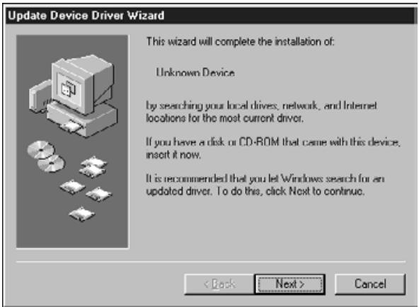
then click on Finish.
-
This dialog box may appear several times.
-
Insert the Dimâge Scan Dual2 CD-ROM into the CD-ROM drive.
-
Select Run from the Start menu.
- Select D:\Driver\English\Setup.exe from the Open drop-down list, then click on OK.
- If your CD-ROM drive is not the D drive, replace the D with the appropriate designation for your CD-ROM drive.
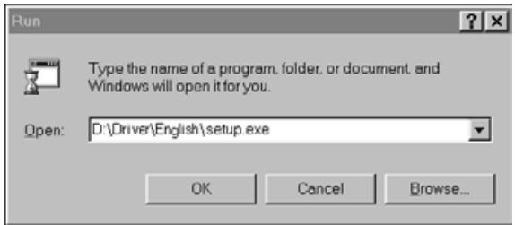
The Run dialog box will appear.
The installer flash will appear.
- Click on Next.
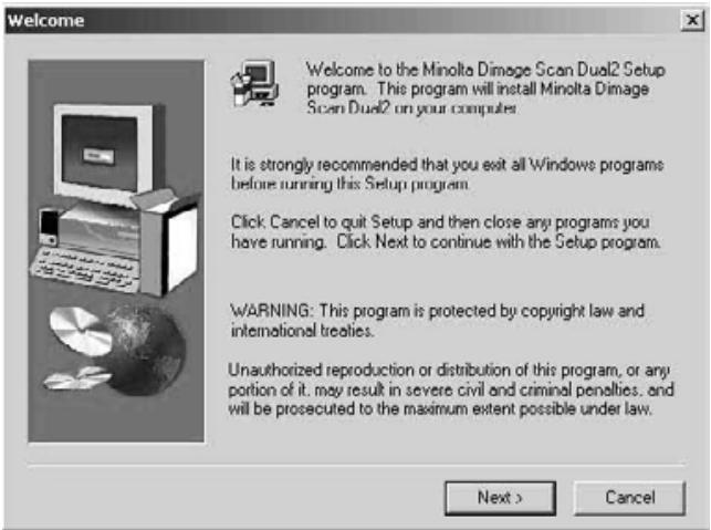
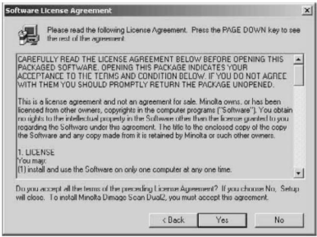
The Software License Agreement will appear.
-
After reading the agreement, click on Yes.
-
If you do not agree to the conditions stated in the End-User License Agreement, click on No and the software will not be installed.
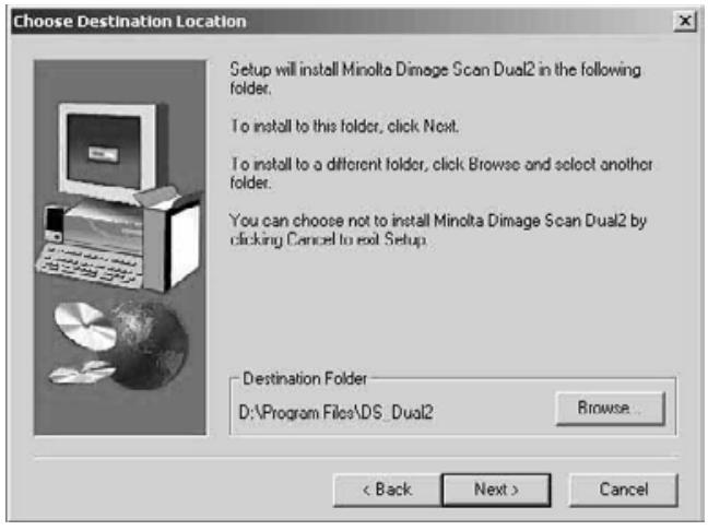
The Choose Destination Location dialog box will appear.
-
Click on Browse to select another destination directory...
-
An install directory and path can also be entered directly into the install path list box.
then click on Next.
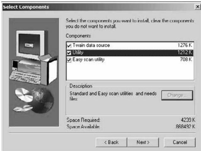
The Setup Type dialog box will appear.
- Choose either Typical or TWAIN Files install, then click on Next.
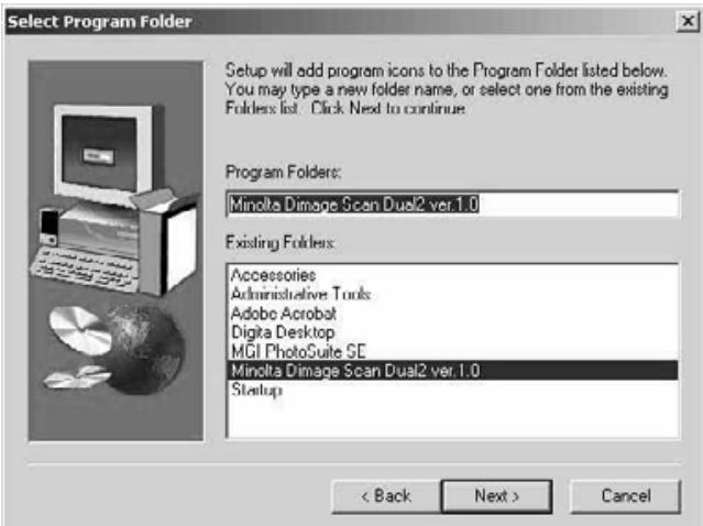
The Select Program Folder dialog box will appear.
10. Click on Next.
- Setup will begin.
The Setup Successful dialog box will appear.
- Click on Close.
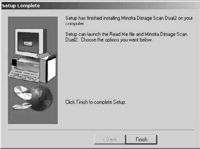
- Click on Finish.
Please remove or disable any antivirus system extensions before launching this installer. These extensions may conflict with the operation of this installer. Replace or re-enable them when installation is complete. Hold the shift key down during startup to disable the extensions.
- Turn on the Dimâge Scan Dual2, then turn on your Macintosh.
- Quit any open applications.
-
Insert the Dimâge Scan Dual2 CD-ROM into the CD-ROM drive.
-
DS will appear on the desktop.
-
Double-click on
-
The driver folders will appear.
-
Double-click on Driver folder.
-
The language folders will appear.
-
Open the English language folder, then double click on the Dimâge Scan Dual2 Installer.
-
The installer's start-up screen will appear.
-
Click on Continue
-
Click on Accept
-
If you do not agree to the conditions stated in the End-User License Agreement, click on Decline and the software will not be installed.
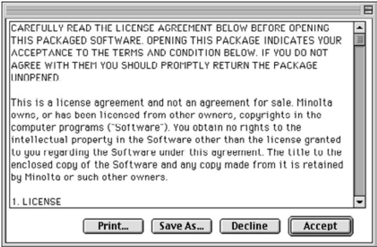
The End-User License Agreement will appear.
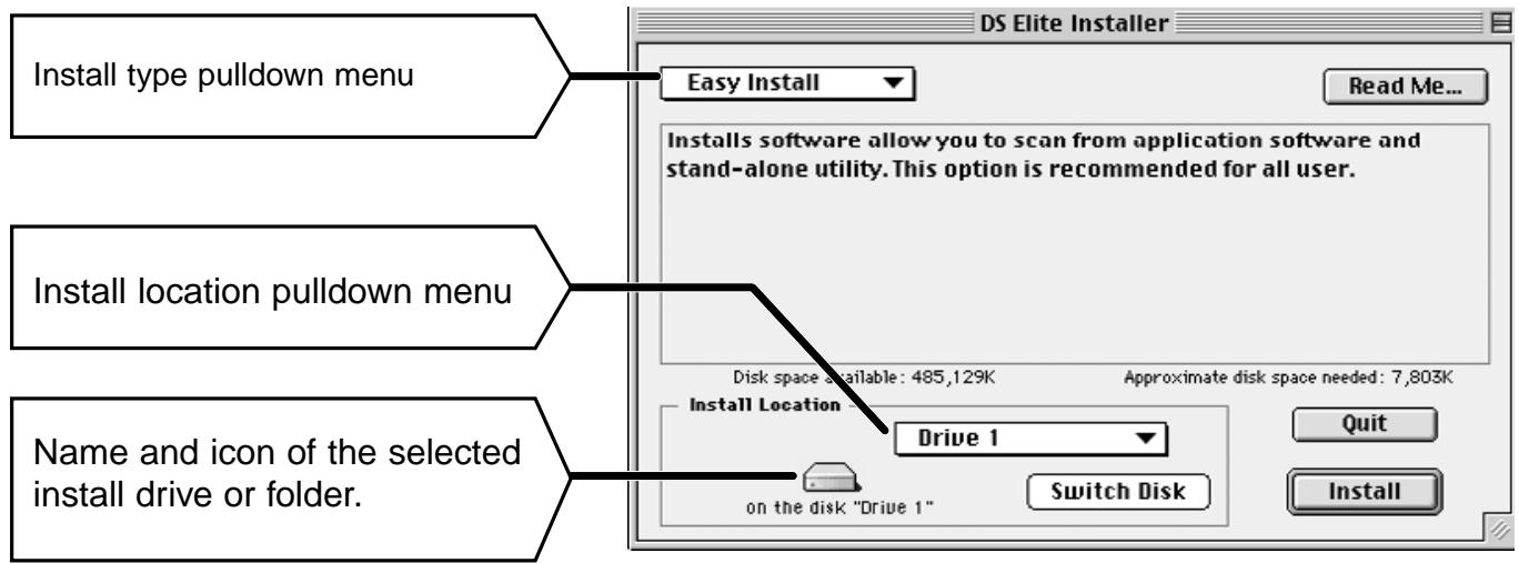
The following dialog box will appear.
9. Select the install drive (or folder) and type from the pulldown menus.
- You can also click on Switch Disk to select an install drive.
10. Click on Install
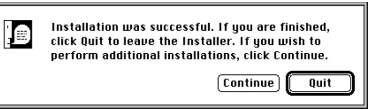
The following message appears when the installer is finished.
11. Click on Quit
- The software will be installed in a new folder titled DImage Scan Dual2.
- If Easy Install was chosen, the DimAge Scan Dual2 folder will contain the following items: DS_Dual2 Utility, DS_Dual2 Plug-in, and Read Me file.
- Your Macintosh will automatically restart.
12. Drag the DS Dual2 Plug-in to the Import/Export folder in the Adobe Photoshop Plug-ins folder.
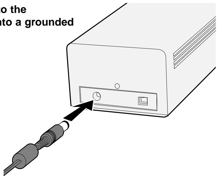
Connecting the AC power adapter and the USB Cable.
This scanner has been packaged with the USB cable and AC power adapter.
- Plug the AC power adapter cord into the scanner's AC socket, then plug it into a grounded outlet.
- Connect one end ( ) of the USB cable to either USB port on the back of the scanner.
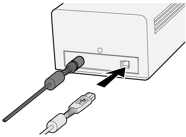
Continued on the following page
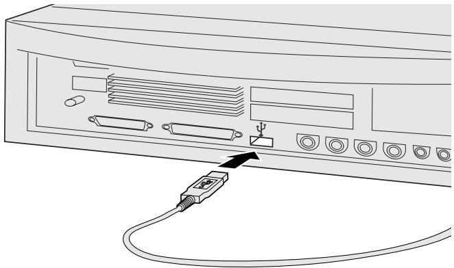
- Connect the other end of the USB cable ( ) to the USB port on the computer or the USB Hub terminal.

NOTE:
When connecting the Dual2 with the USB hub terminal, be sure to connect to the closest terminal to the computer.
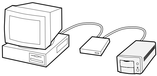
Example: Connect the USB Hub terminal
EASY SCAN UTILITY
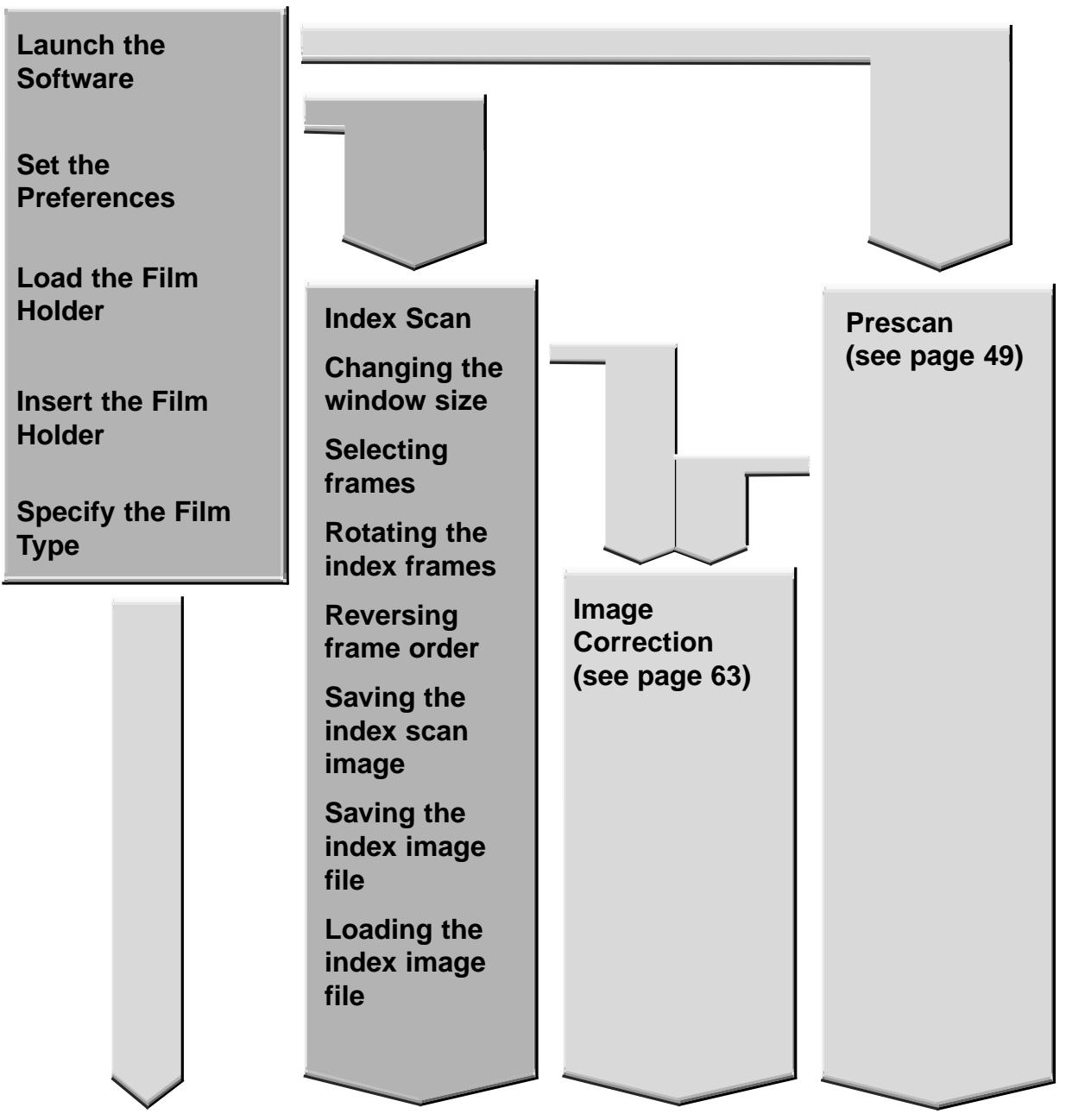
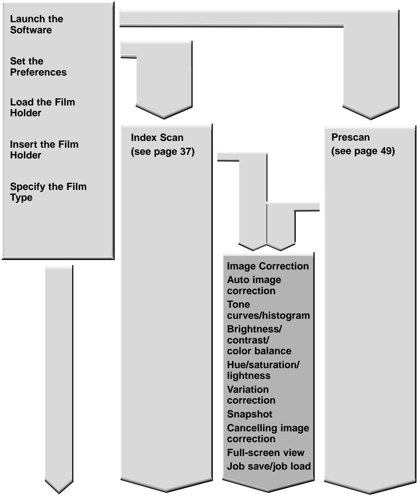
EASY SCAN UTILITY FLOW
Launch the Software
Set the Preferences
Load the Film Holder
Insert the Film Holder
Specify the Film Type
Sample Index Scan
Specify the Job Type
Saving Easy Scan Utility
WINDOWS 98/WINDOWS 2000
Starting up the utility software
The Minolta Easy Scan Utility can be performed by using the utility software.
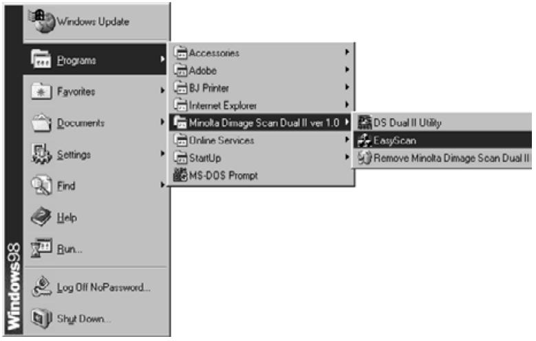
1. After performing steps 1 and 2 on page 36, select Start > Program (P) > Minolta Dimâge Scan Dual2 ver.1.0 > EasyScan.
- The software starts up and the Easy Scan Utility window will appear.
MACINTOSH
Starting up the utility software
The Minolta Easy Scan Utility can be performed by using the utility software.
1. After performing steps 1 and 2 on page 36, double-click on the Dimâge Scan Dual2 ver. 1.0 folder and then double-click on EasyScan.
- The software starts up and the Easy Scan Utility window will appear.
Easy Scan Utility Window
While the Minolta Easy Scan Utility software is functioning, the following window is displayed.
The Easy Scan Utility Window – Name of parts
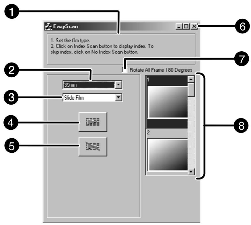
Operation Step display
Film Type list box
3 Film Format list box
Perform Index Scan
Do not Perform Index Scan
Close button (The upper left side of the window on Macintosh)
7 Rotate 180^ check box
Index Image Frame
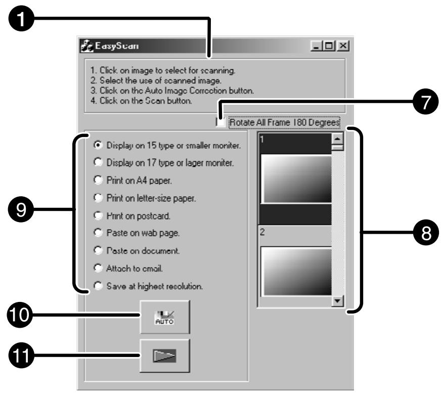
Setting Image Usage check box
10 Correct image automatically button
11 Scan button
Using the included 35mm negative and slide holders, the Minolta Dimâge Scan Dual2 can scan mounted or unmounted...
-
35mm color negatives
-
35mm color slides
-
35mm black & white negatives
-
35mm black & white positives
APS (Advanced Photo System) negatives and slides can also be scanned using the optional AD-10 APS Adapter. See page 28.
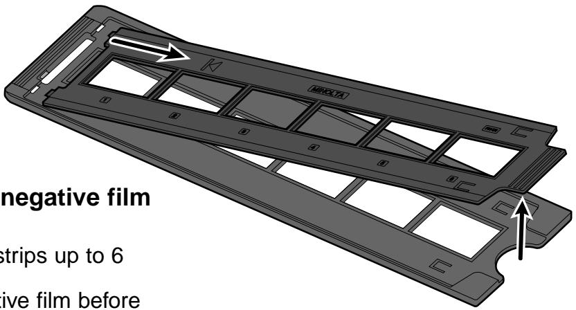
Loading the 35 mm Negative Film Holder – FH-U1
- Open the film cover on the 35 mm negative film holder by lifting the film number "6" side of the film cover.
-
Place the film in the 35mm negative film holder emulsion side up.
-
The film holder will accept film strips up to 6 frames long.
- Brush dust off the 35mm negative film before placing it into the film holder.

NOTE:
The frame numbers and text are reversed when the film's emulsion side is up.
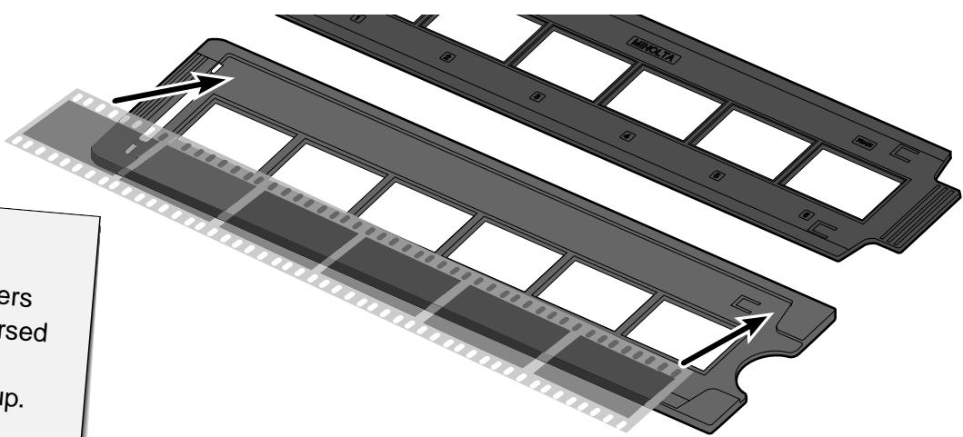
- Align the frames within the scanning windows.
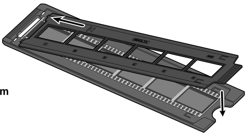
- Snap the 35mm negative film holder closed.
Loading the Slide Mount Holder - SH-U1
- Insert slides into the slide mount holder emulsion side up.
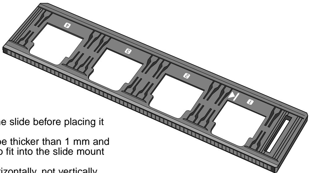
- Brush dust off the the slide before placing it into the film holder.
- Slide mounts must be thicker than 1mm and thinner than 2mm to fit into the slide mount holder.
- Orient the slides horizontally, not vertically.

NOTE:
- Do not scan glass mounted slides. Glass mounts bend the light from the line scanner, producing bad results.
- The APS positive film placed in the slide mount holder can be scanned using the supplied holder in the AE Off and 35 mm Color Positive film settings.

The AD-10 APS Adapter is an optional accessory. The Dimâge Scan Dual2 can not scan Advanced Photo System film (IX-240 type) without the AD-10 APS Adapter.
Names of Parts
1 Film-chamber door
Film-chamber release
3 Scanner contacts*
- Do not touch
Loading the APS Adapter
-
Slide the film-chamber release as shown.
-
The film-chamber door will open.
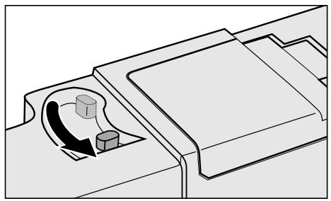
-
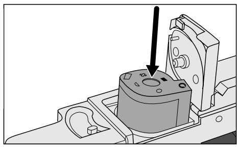
Insert the film cassette into the film chamber with the VEl on top.
-
Only load cassettes with the ■ mark current.
-
Close the film-chamber door.
-
The film-chamber door will not close if the ■ mark is not current. Forcing the door shut could damage the cassette.
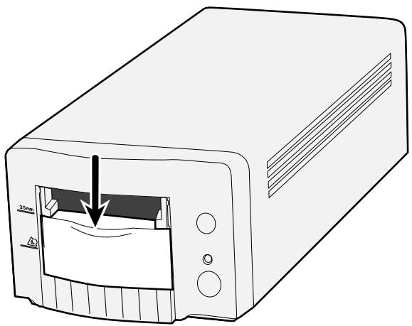
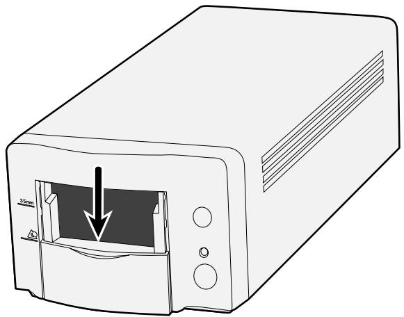
During the start-up time, the indicator lamp will blink. DO NOT insert the film holder into the film slot until the indicator lamp is steady.
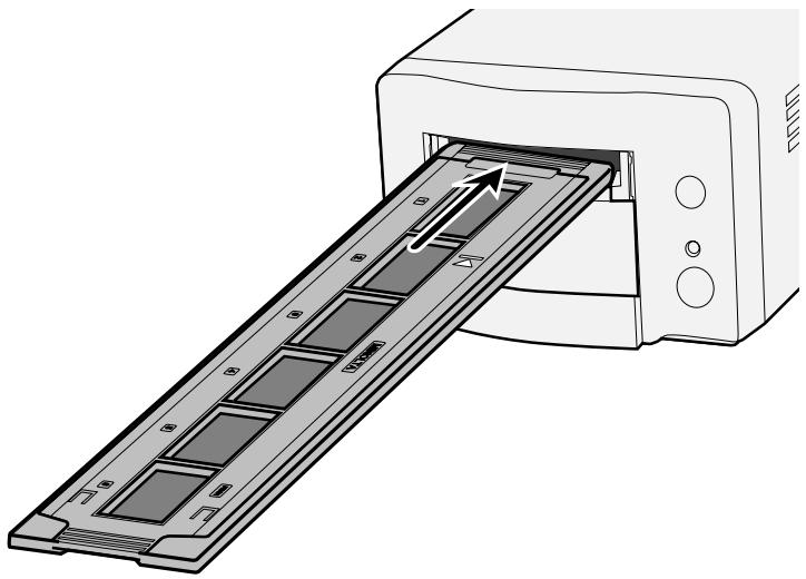
Scanning with the FH-U1 35 mm film or SH-U1 slide film holder
- Open the scanner lid by pushing it down to the 35 ~mm mark 35 ~mm .
- Be sure that the white arrow mark on the 35 ~mm film or slide film holder is facing up and then insert the 35 ~mm film or slide filme holder into the scanner up to the arrow mark.
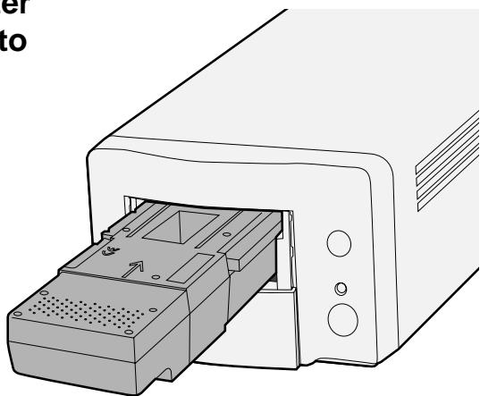
- Open the scanner lid by pushing it down to the APS mark
- Be sure that the arrow mark on the APS adapter is facing up and then insert the APS holder into the scanner until the holder stops.
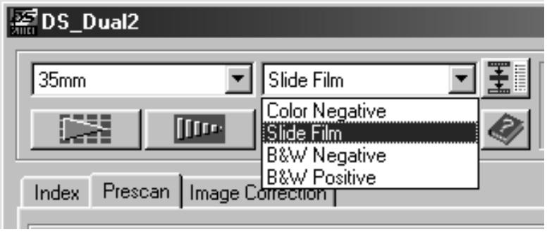
Selecting the film type
1 Select the film format to be scanned in the Main window.
2 Select the film type.
- The index tab is selected and the index window will appear.
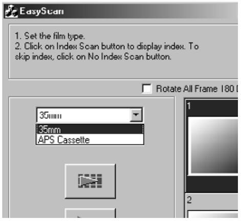
1. Select whether the index scan should be perform or not.
- When Perform the index scan' is selected, the index scan starts. When 'Not Perform the index scan' is selected, the window changes to the scan window.
Setting the usage
- Select the image usage setting from the radio button list displayed in the scan window.
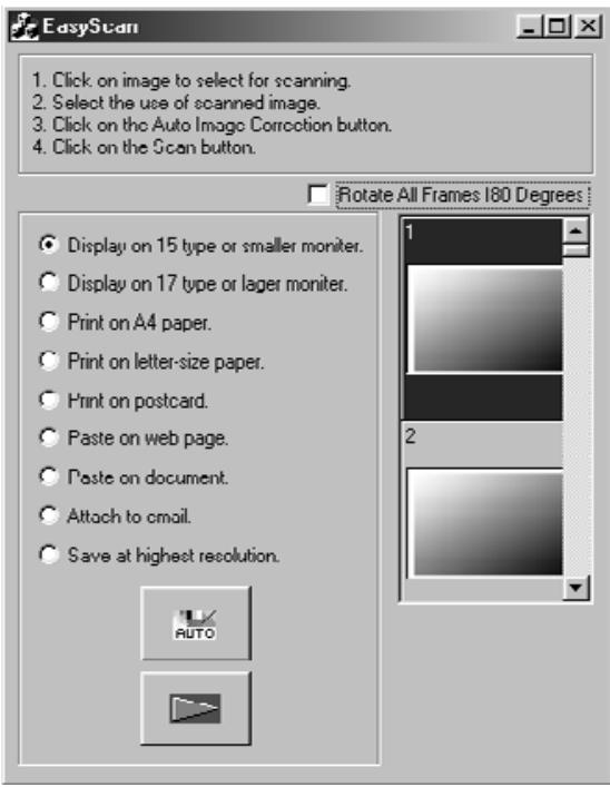
Image Correction
-
Perform the auto image correction using the 'Auto Image Correction' button if necessary.
-
The image correction matching to the image will be applied automatically.
Rotate
- Rotate the image 180^ if necessary.
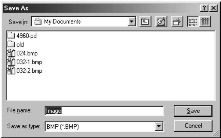
1. Click on the Scan button to scan.
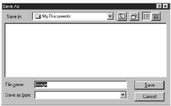
- When the 'file saving dialog box' appears, select the file format and save the scan.
File format: BMP JPEG,TIFF (Windows)
PICT, JPEG, TIFF (Macintosh)
INDEX SCAN
SCANNING FLOW
Scan and Save (see page 83)
The TWAIN driver allows you to control the software through another application, such as your image editing software.
Launching the TWAIN Driver – Windows
This manual uses Adobe Photoshop LE as the host application. Commands may vary among applications.
- Open the host application.
- Select File > Import > Select TWAIN_32 Source...

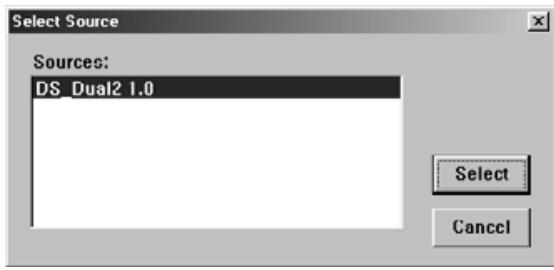
The Select Source dialog box appears.
- Select DS_Dual2 1.0, then click on Select.
- Select File > Import > TWAIN_32.
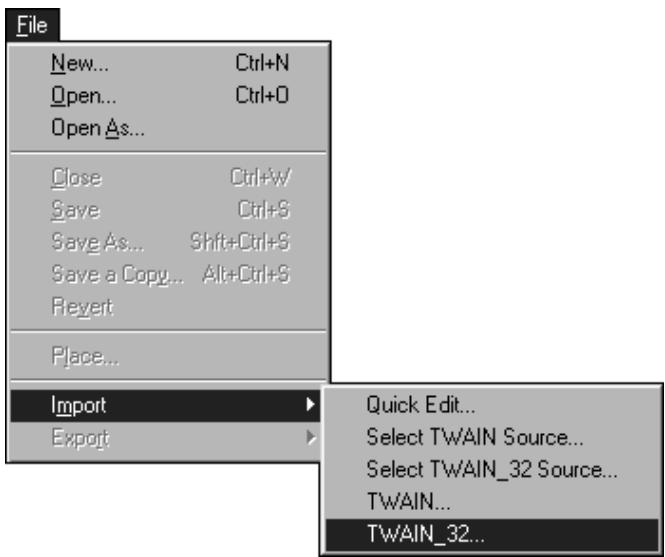
The software is ready for use when the Main window appears (page 38).
The plug-in software lets you access the software through Adobe Photoshop.
Launching the Plug-in – Macintosh
- Launch Adobe Photoshop.
- Photoshop LE, 4.0.1 and newer: Select File > Import > DS_Dual2 Plug-in. Photoshop 3.0.5: Select File > Acquire > DS_Dual2 Plug-in
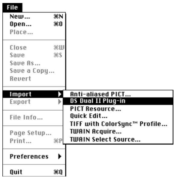
The software is ready for use when the Main window appears (page 38).
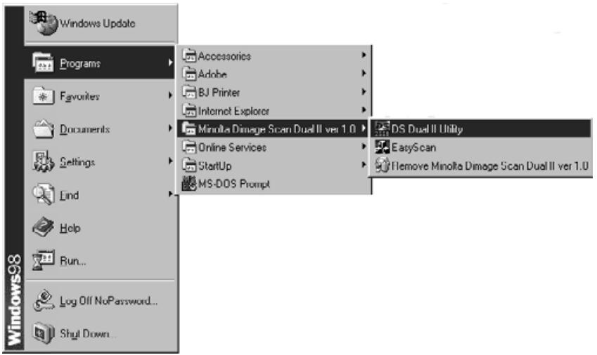
Use the utility software, as a stand alone application, when you just want to scan the photographic image and store.
Launching the Utility Software
Windows
Select Start > Programs > Minolta Dimâge Scan Dual2 ver.1.0 > DS Dual II Utility
Macintosh
Double click on
The software is ready for use when the Main window appears (page 38).
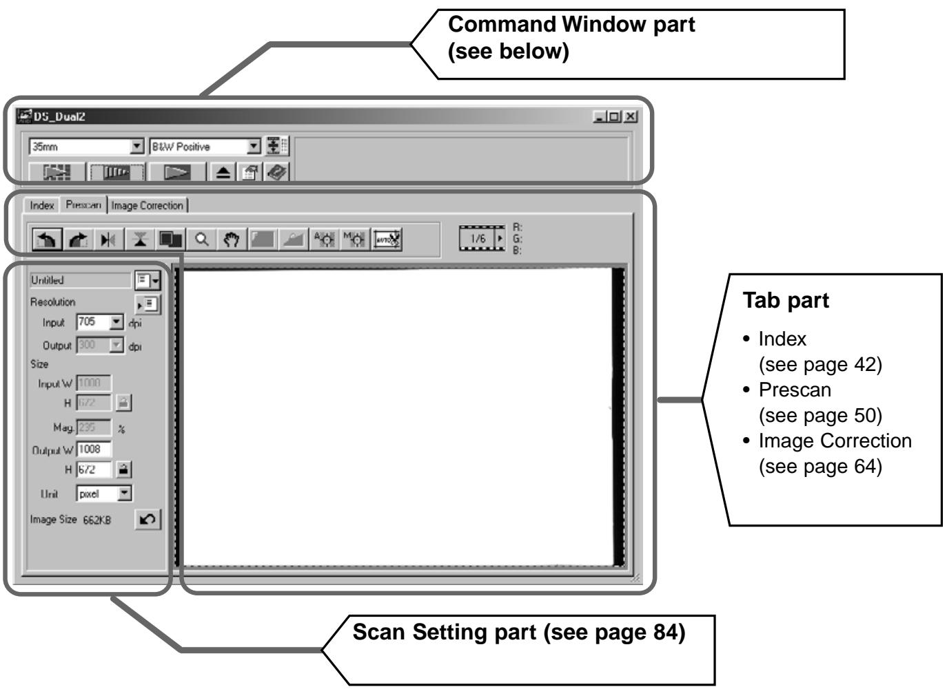
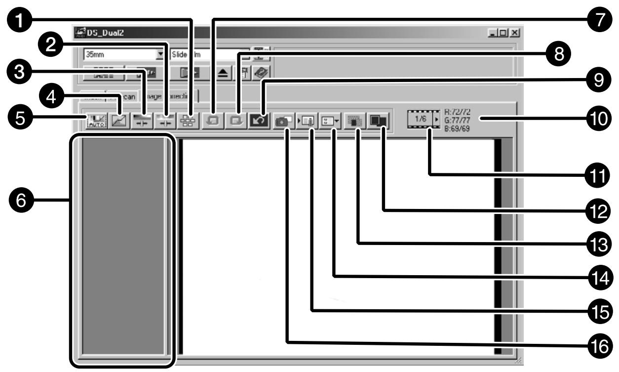
MAIN window
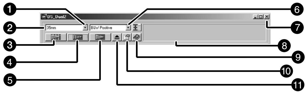
The Command window part – Name of parts
1 Film Type list box
Film format list box
3 Index Scan button
Prescan button
5 Scan button
Navigation button
Close button
8 Status bar
Help button ( on Macintosh)
10 Preferences button
Eject button
1. Click on in the Command window.
The Preference Dialog Box – Name of parts

2. Set the preferences as desired.
1 Auto Expose for Slides checkbox
Select this checkbox when scanning underexposed slides.
2 Scan AF checkbox
Select this checkbox to use the auto focus function when performing the index scan, preview scan and AF scan.
3 Close Driver After Scanning checkbox
Closes the scanner's driver software after the scan is complete.
Color depth setting box
The pixel depth of each color channel used to scan your image (RGB or CMY).
Three options are available:
8-bit over 16.7 million colors
16-bit over 2.8 billion colors
- 16-bit linear -- same as 16 bit, but image correction is not applied when the image is scanned.
5 Index Scan priority
Speed - Creates a thumbnail representation of each frame on the roll.
Quality - Thumbnail and Prescan images are created for each frame on the roll.
Double-clicking on the index image opens the ready-made prescan image.
3. When scanning APS, set the Preferences as desired in the APS settings part.
- De-select the Close Driver After Scanning checkbox when scanning multiple images at the same time.
6 Auto film rewind
Clicking on the Rewind button in the Command window automatically rewrites the film into the APS cassette before the APS adapter is ejected.
7 Rotate All Frames 180 Degrees
Rotates all frames in the Index window 180^ .
4. Click on OK to accept the new preference settings.
Changes to the Preference settings take effect immediately.
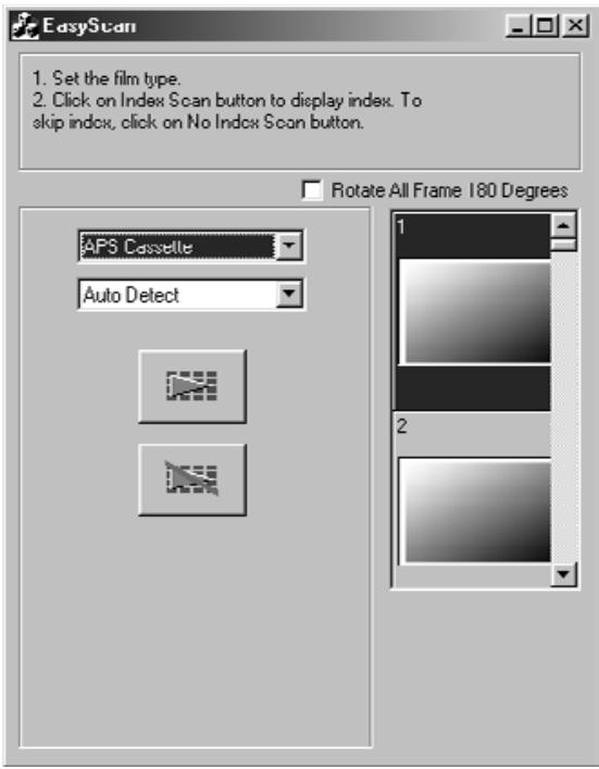
- Insert the holder into the scanner.
- Select 35mm or APS Cassette from the film format drop-down list in the Command window.
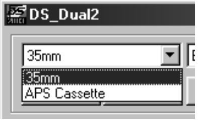
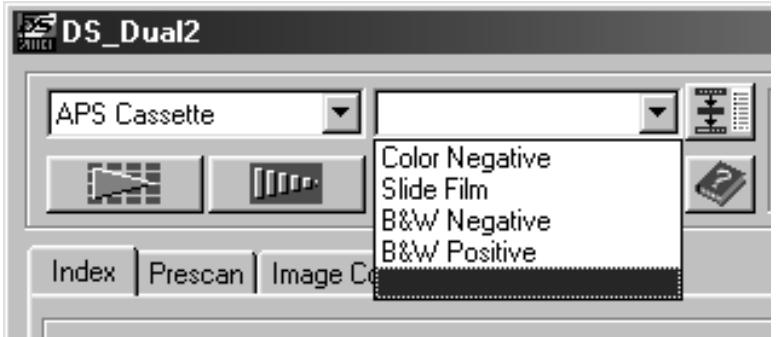
- Select the film type from the film type drop-down list.
Select APS Cassette
Index scan displays a scan of each image on the film holder in the Index tab. The time required for an index scan depends on the performance of your computer.
If you don't want to index scan the entire roll, select the frame number of the image you want to scan from the index print provided by your photofinisher. Click on the appropriate image box in the index tab to select an image for prescanning or scanning.
- When APS is selected in the Command window, there are two options for making an index scan are available Speed or Quality. Select the desired option in the Preference dialog box (see page 39).
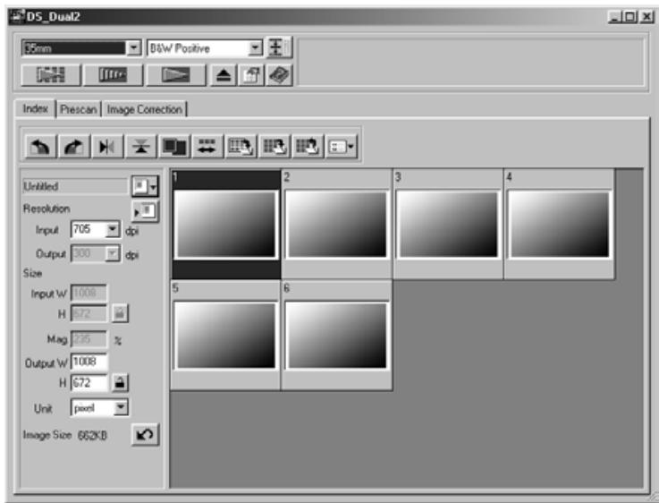
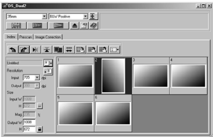
Click on Index tab in the Main window.
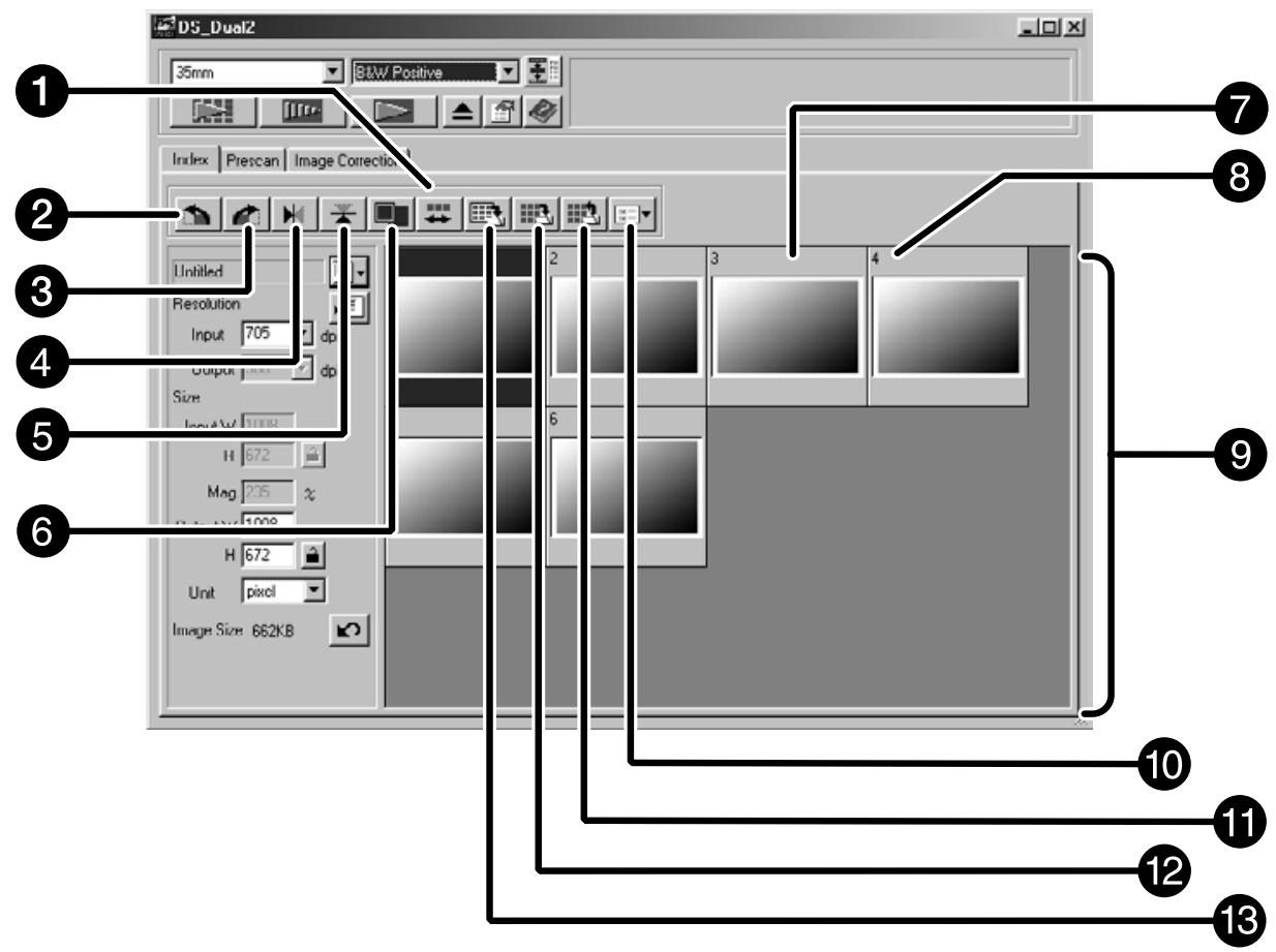
The Index tab part – Names of Parts
1 Reverse frame order button
Rotate left button
3 Rotate right button
4 Flip Horizontal button
Flip Vertical button
6 Full-Screen View button
Index Image frame
8 Frame number
9 Index Image area
10 Image Correction Job Load button
Save Index Image button
12 Index Load button
Save Index scan button
Index scan
1. Click on in the Command window.
- All frames on the film folder will be scanned and appear in the Index tab.
NOTE:
- To cancel the index scan, press the escape key (Command and period for the Macintosh) until the Cancellation Index Scan message box appears.
The completed index scans will appear in the Index tab
- Frames that have not been index scanned can still be selected for prescanning and scanning.
Changing the Window Size
Change the size of the Index tab window as desired. The position of the frames will change accordingly.
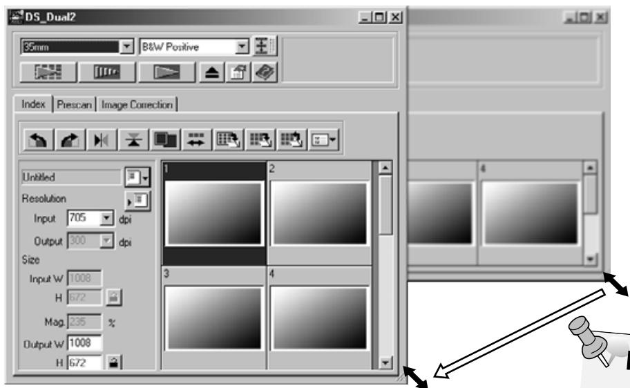
NOTE:
- When the Full-Screen View button is not clicked, the size and shape of the index frames do not
-
When the Full-Screen View button is clicked, the size of the index frames changes automatically and all frames are displayed.
-
Click on the corner tab (lowerright corner) and drag to reach the desired size.
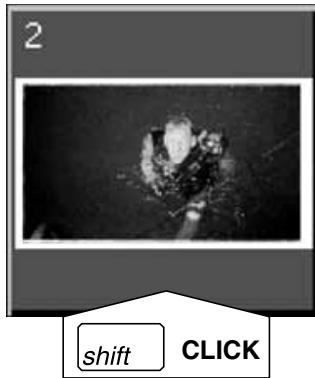
Selecting Frames
1. Click on an image to select it for scanning.
- Selected images are surrounded by a dark gray frame.
- Press the control key (key for the Macintosh) while clicking to select additional frames for scanning.
- Press the control key (key for the Macintosh) while clicking to deselect an image.
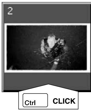
- Press the shift key while clicking to select all the frames between the current frame and the last frame selected.
2. Click on to scan the selected image (s).
- The scan is cancelled if more than the number of frames selected is greater than the Max # of Frames set in the Preferences dialog box. See page 39.
- The image will be opened in your photo application software when the scanner's driver software is closed.
- Some photo applications can only acquire one image at a time.
3. Refer to page 46 to save the scanned image(s).
- Multiple scans will be saved using the selected file name and numbered chronologically. Example: File_Name01, File_Name02, File_Name03...

NOTE:
Click on to save the index as an image file.
The image can be saved in JPEG or BMP format (JPEG or PICT format for the Macintosh).
Rotating the Index Frames
Rotate index frames so they appear in the Index scan tab window with the proper orientation.
-
Select the desired frames, then click on 山 , 山 or 山 , 山 .
-
The selected frames will rotate in 90^ increments either clockwise or counter-clockwise or flip vertically or horizontally.
- Rotating the index frame will not affect the Prescan or Scan.
Reversing Frame order
Some cameras are reverse-winding, so the last frame is exposed at the beginning of the roll. The order of the Index tab can be reversed to correct the chronology.
- Click on .
When performing the index scan, all the thumbnail images displayed in the index window can be saved as an image file.
1. Click on the 'Save Index Image' button in the Main window.
- The standard file save dialog box for each operating system will appear.
[Windows®]
- For Windows®, the file can be saved in the Windows® Bitmap (BMP) or JPEG format.
[Macintosh]
- For Macintosh, the file can be saved in the PICT or JPEG format.
2. Enter the desired file name, select the file destination and then click on Save.
- All the thumbnail images in the index window will be saved in the selected location with the specified file name.
- For Windows®, the file can be saved in the Windows® Bitmap (BMP) or JPEG format. For Macintosh, the file can be saved in the PICT or JPEG format.
Some index images displayed in the index tab can be saved as an index file.
1. Click on the 'Save Index' button in the Main window.
- The standard file save dialog box for each operating system will appear.
[Windows®]
- For Windows®, the file can be saved in the Windows® Bitmap (BMP) or JPEG format.
[Macintosh]
- For Macintosh, the file can be saved in the PICT or JPEG format.
2. Enter the desired file name, select the file destination and then click on Save.
- When the index images are displayed, these images are saved regardless of the film set in the scanner.
- When the index images are not displayed, the index images are saved after performing the index scan.
- If there are index images which have not been scanned yet, those images will be scanned and then all index images including those images will be saved.
The index file can be displayed in the index tab after reading the saved index file. The previously displayed preview images are erased.
1. Click on the 'Read Saved Index' button in the Main window.
- The standard file open dialog box for each operating system will appear.
[Windows®]
- For Windows®, the file can be saved in the Windows® Bitmap (BMP) or JPEG format.
[Macintosh]
- For Macintosh, the file can be saved in the PICT or JPEG format.
2. Select the index file to be read and then click on OK.
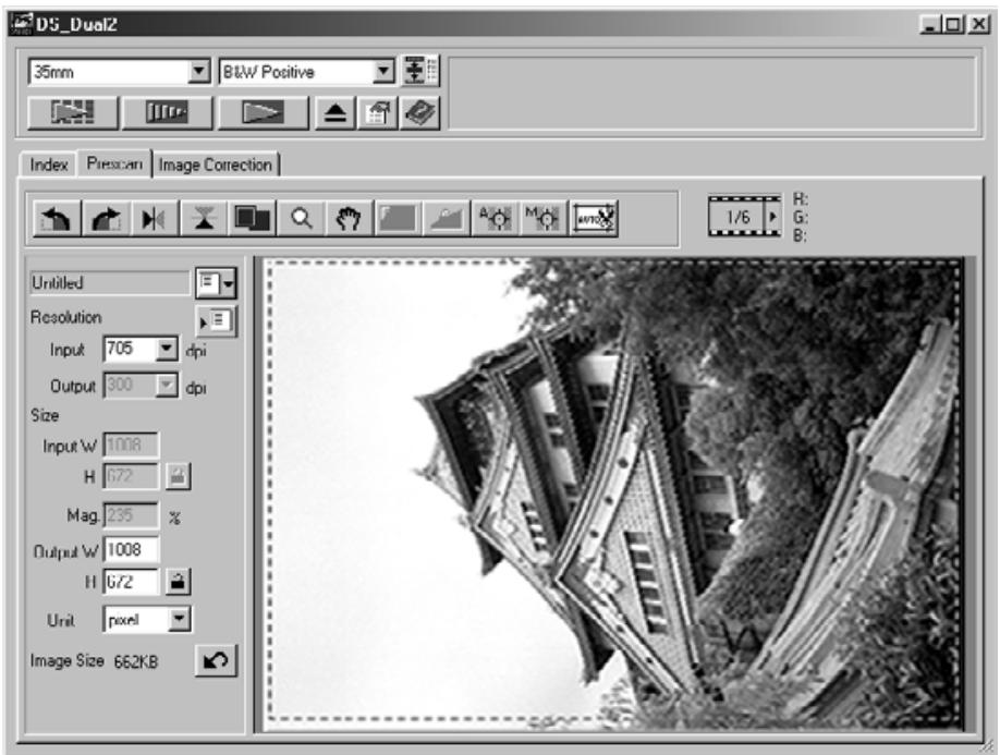
PREVIEW SCAN
SCANNING FLOW

Scan and Save (see page 83)
Prescanning creates a scan of the image that you can apply and view color, contrast, orientation, and brightness corrections before clicking on the Scan button. This ensures that final scan will be the best it can be.
Click on the Prescan tab in the Main window.
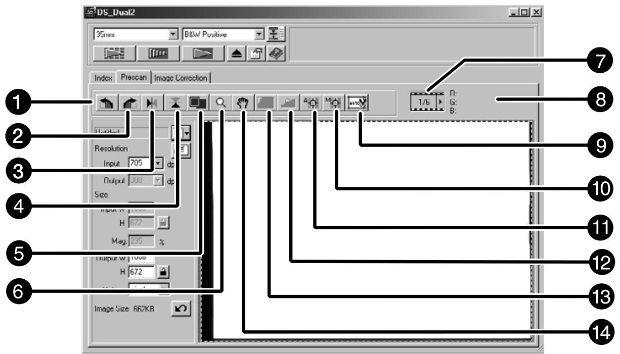
The Prescan tab part – Names of parts
1 Rotate Left button
2 Rotate Right button
3 Flip Horizontal button
4 Flip Vertical button
5 Full-Screen View button
6 Zoom button
7 Frame number indicator
8 RGB/CMY display
Auto Holder/Mount Crop Adjustment button
10 Manual Focus button
11 Point AF button
12 AE Lock button
AE Area Lock button
14 Grab button
1. Click on in the Command window.
The prescanned image will appear in the Prescan tab.

NOTE:
Press Ctrl when prescanning (on the Macintosh) to see CMY values in the RGB/CMY display.
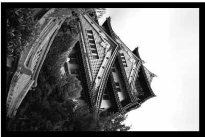
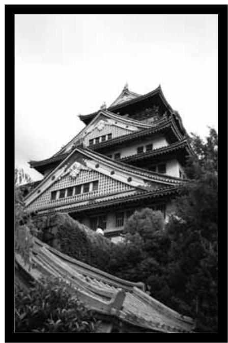
Rotate
Click on the and buttons to correct the orientation of your image before scanning. Changes will be reflected in the prescan image.
Click on to rotate the image 90^ clockwise.
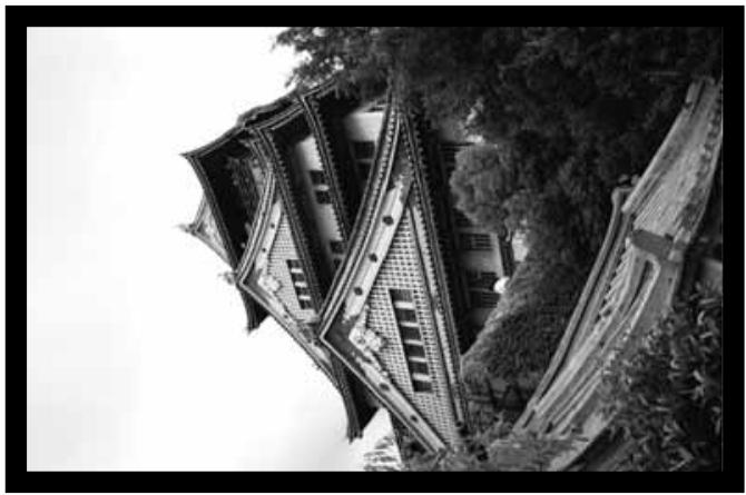
Click on to rotate the image 90^ counter-clockwise.

Flip
The and buttons let you flip the image left to right or top to bottom before scanning. Changes will be reflected in the prescan image.
Click on to flip the image top to bottom.

- The image is upside down compared to the original prescan.
Click on to flip the image left-to-right.
- Image is reversed compared to the original scan.
Full screen view
This function allows you to display the entire prescanned image in the Prescan tab.
1. Click on
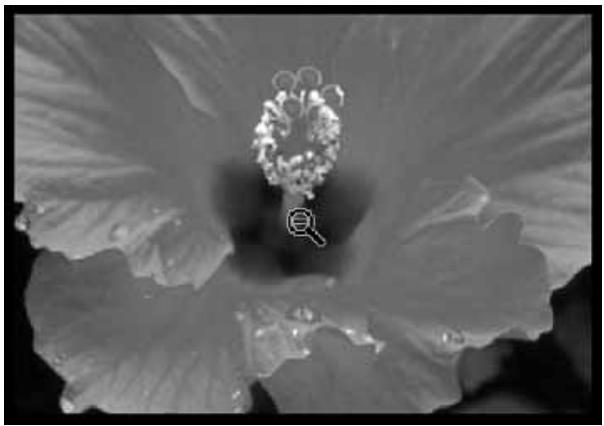
Magnifying or Reducing the View
Use the zoom button to increase or reduce the image magnification.
Zooming In
1. Click on Q .
- The pointer will change to 假
2. Click anywhere on the image to zoom in.
- The clicked position will be the center of the magnified view in the Prescan tab.
- The "+" disappears from the magnifier icon when the maximum image magnification has been reached.
Zooming Out
1. Press and hold the Ctrl key (option key on the Macintosh) to reduce the image magnification.
- The pointer will change to Q .
2. Click anywhere on the image to zoom out.
- The “-” disappears from the magnifier icon when the minimum image magnification has been reached.
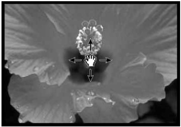
Scroll
Use the grab button to scroll an enlarged image.
-
can only be selected when the image has been magnified beyond the limits of the Prescan tab.
-
Click on 7 in the Prescan image display area.
The pointer will change to ^ .
- Click on and drag the image to the desired location.
Especially useful when scanning bracketed exposures, AE (auto exposure) lock lets you scan multiple images with the same initial exposure settings. AE Lock saves the automatic exposure settings determined when an image is prescanned. Subsequent images are prescanned using the 'locked' exposure settings.
- AE-lock does not save exposure corrections made in the Variations, or Tone Curves and Histogram dialog box.
Setting AE-Lock
After rescanning the image...
1. Click on
- can not be selected until an image has been prescanned.
2. Select another image, then click on
- The scanner skips the setting exposure step in the prescan sequence.
Images will be scanned using the AE lock settings until AE lock is cancelled or the scanner is reinitialized.
Cancelling AE-Lock
1. Click on
- Click on to prescan the image again.
The AE area in auto exposure adjusting mode can be changed and the exposure of that area is adjusted automatically.
Perform the procedure below after prescanning the image.
1. Click on
2. Press the Shift key.
- The AE area is indicated by a line instead of the cropping area indicated by a dashed line.
3. While pressing down the Shift key, change the AE area.
- The operation is the same as that of changing the cropping area except that the shift key should be used.
- For details, see "Cropping" (see page 60).
Focus
The Dimage Scan Dual2 uses the CCD sensor for autofocus.
Autofocus uses the center of the image to determine focus. Normally, this results in an excellent scan because the film plane is flat. However, if the film is warped or curled, or if Autofocus is turned off in the preferences, focus may not be accurate. In this case, the focus adjustment should be performed again using the pont AF or Manual Focus function.
- Automatic autofocus can be turned on and off in the Preferences (page 39).
POINT AF
This allows you to use autofocus on a specific area of the image.
-
Click on
-
The pointer will change to the Point AF icon.
-
Click on the Point AF button again to escape the function.
-
Click on the area of the image to be in the sharp focus.
-
Autofocus will begin, then a new prescan will start.
- The prescanned image will appear in the Prescan window when complete.

NOTE:
For best results when using Point AF and Manual Focus, click on an area with contrast or detail. Manual Focus and Point AF will no be able to focus on an area with flat color (such as a gray sky or solid black subject).
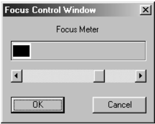
MANUAL FOCUS
Use manual focus on a specific area of the image or to reduce the appearance of grain in grainy film (such as high-speed or pushed film) by slightly defocusing it.
1. Click on
- The pointer will change to the Manual Focus icon.
- Click on the Manual Focus button again to escape the function.
2. Click on the area of the image to be in sharp focus.
- The Focus Control Window dialog box will appear.
3. Adjust the slider until the black and gray lines are at their longest for maximum focus.
- Click and drag the slider to the left and right. Click on the slider bar to make a larger change.
- To slightly defocus, adjust the sliders until the black bar is a little shorter than the gray bar.
4. Click on OK
- A new prescan will begin.
- The prescanned image will appear in the Prescan tab when complete.
Auto Cropping
The cropping area is determined automatically so that the holder or slide mount frame in the prescan image is removed.
Click on autor.
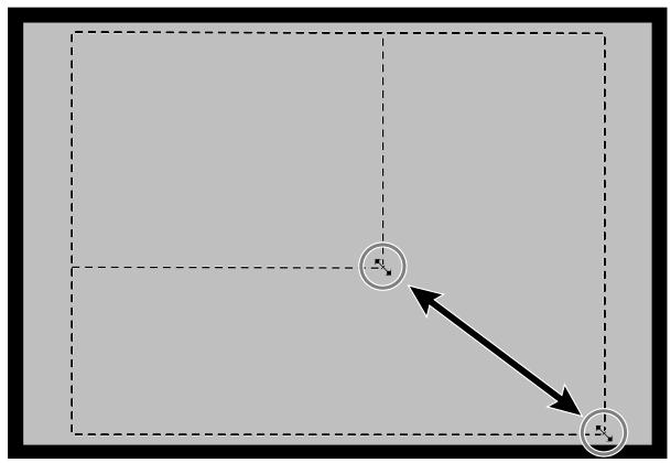
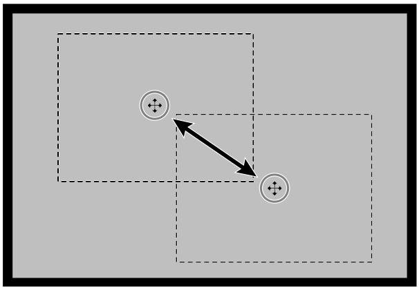
Cropping
The cropping frame defines how much of the prescan image will be scanned. The dimensions of the cropping frame are displayed in the lower left corner of the Prescan tab.
To enlarge or reduce the size of the cropping frame...
Click on the cropping frame and drag the pointer in or out.
- Click on the corners and drag to resize the cropping frame proportionally.
- Click on the sides and drag to resize the cropping frame non-proportionally.
To move the cropping frame...
Click inside the cropping frame, then drag the cropping frame to its new location.
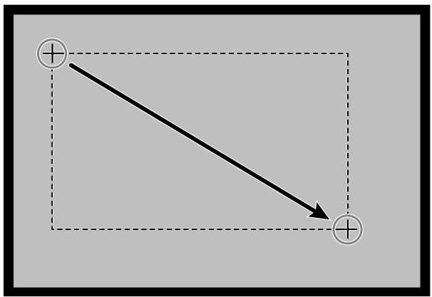
To define a new cropping frame...
Click and drag outside the current cropping frame.
- Click on an image or an image box, then click on the image. The image will be prescanned, then opened in the Prescan tab.
- Orient and crop the image as desired (see page 52 to 57, 60).
- Apply contrast, brightness, and color corrections (see page 65 to 77).
-
Select the desired job type (see page 84 to 88).
-
Only one job type can be selected when multiple images are scanned at the same time.
-
Close the Prescan tab window to return to the Index tab window.
-
Adjustments made in the Prescan tab are held until the image is scanned or the driver software is closed.
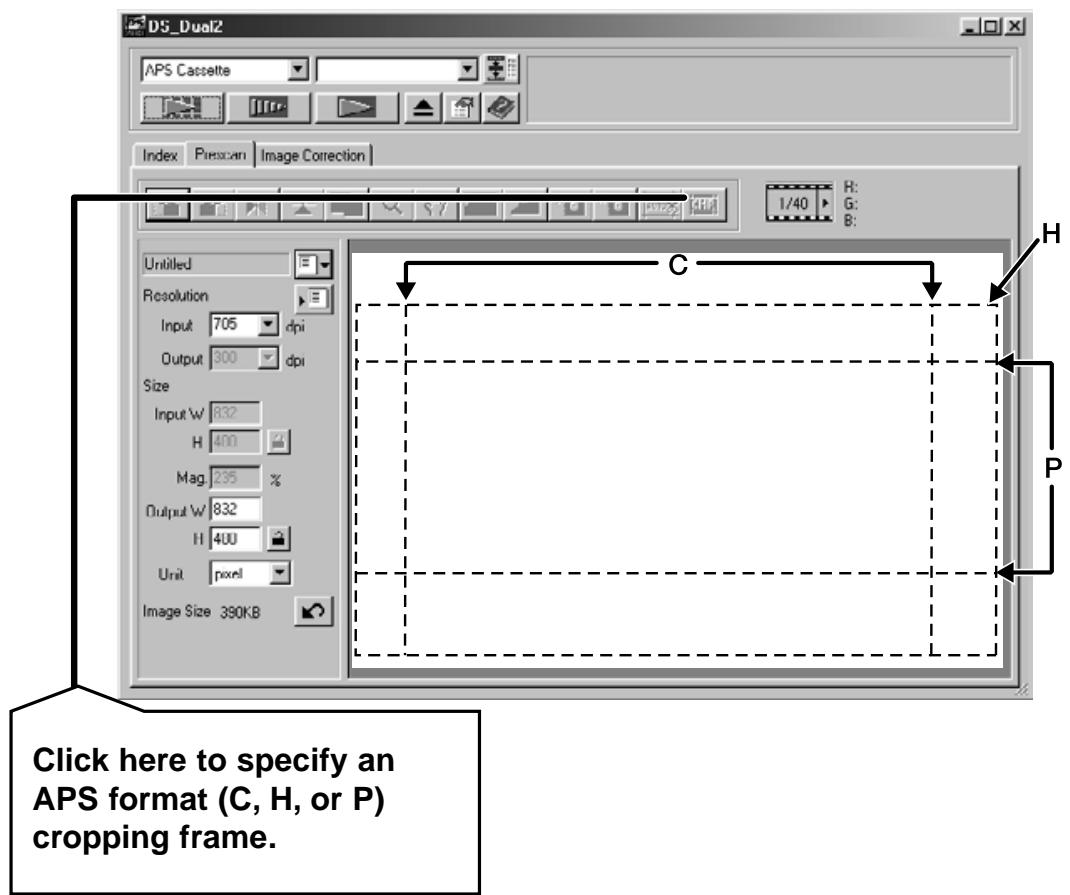
APS formats; C, H and P (APS only)
When APS is selected in the Main Window, the CHP button allows you to quickly and easily define the cropping frame by the standard APS format; C, H and P.
1. Click on to display the APS cropping frames.
- The cropping frames are displayed in sequence with each click of the CHP button.
RGB/CMY information
The RGB information from the pointer position is always displayed in the Prescan tab. The information is described in brightness levels from 0 to 255. However, the display can be changed to show CMY information.
1. Press and hold the Shift key (command key on the Macintosh) with the Prescan tab open. The RGB information will change to CMY.
Displaying Frame number
This function allows you to display the current frame number and total frame number.
- To display the next frame, click on .
- To display the previous frame, click on .
IMAGE CORRECTION
IMAGE CORRECTION FLOW
Scan and Save (see page 83)
This scanner gives you three options for correcting the brightness, contrast, and color balance of the final scan.
Click on the Image Correction tab in the Main window.
The Image Correction tab part - Names of parts
Variations button
Hue/Saturation/Lightness Correction button
3 Brightness/Contrast/Color Balance Correction button
Tone Curves/Instagram Correction button
Auto Image Correction button
6 Snapshot display area
Undo button
Redo button
9 Correction Reset button
10 Frame Number indicator
RGB value display
12 Full-Screen View button
Pre/Post Correction Comparison Display button
14 Image Correction Job Load button
Image Correction Job Save button
16 Snapshot button
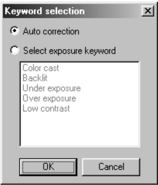
This function automatically performs the ideal correction for each image.
All the corrections performed before clicking on the Auto Image Correction button will be reset. This function is available only when the Color depth is set to "8 bit" in the Preference Dialog box on page 39.
1. Click on

- The Keyword Selection dialog box is displayed.
2. Insert the check mark in the "Select exposure keyword." item.
- To determine the scene to be corrected automatically, insert the check mark in the "Auto correction" and then click on the OK button.
3. Select a scene.
- When selected "Color cast", you can also select another scene.
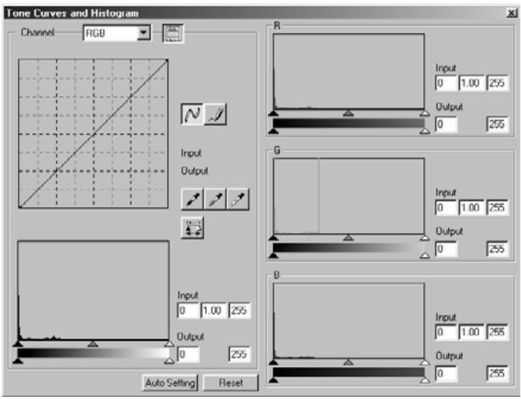
When the Tone curves/Histogram Correction button is clicked, the Tone Curves and Histogram dialog box is displayed.
The Tone Curves part allows you to change the tone curves and directly correct the output value.
The Histogram part allows you to specify the input and output area from the information included in a film and correct images. Also, this dialog box displays the histogram of the image area inside the cropping frame in each RGB color. The level is indicated in 256 color steps (0 to 255) from left to right side.
The tone curves and histogram are linked to each other so that when the tone curve is corrected, the histogram is automatically corrected.
Click on in the Image Correction tab.
The Tone Curves and Histogram Dialog Box – Names of Parts
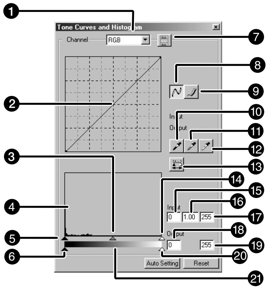
1 Channel Selection list box
2 Tone curves
3 Input Gamma slider
4 Histogram
Input Shadow slider
Output Shadow slider
7 Histogram RGB display button
8 Tone curves/Smooth Curve button
Freehand curve button
10 Black point button
Gray point button
12 White point button
13 Apply button
14 Input Highlight slider
15 Input Shadow text box
16 Input Gamma text box
17 Input Highlight text box
18 Output Shadow text box
19 Output Highlight text box
20 Output Highlight slider
21 Gray scale
Correcting the Tone Curves
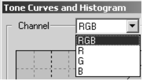
Changing the shape of a correction curve changes the output level for each corresponding input level. Changing the shape of the red, green, or blue curves affects color balance of the image. Changes to the RGB curve affect the image contrast and brightness.
- Click on the arrow next to the channel selection list to display the available channel (R, G, B, RGB).
-
Click and drag the portion of the curve to be changed.
-
Select the channel of the color to be corrected.
-
The coordinate value of the cursor is displayed from 0 to 255.
- The corrected image by changing the tone curves is applied to the prescan image.
- You can also change the tone curves by freehand.
Changing Tone Curves by Freehand
This function allows you to draw tone curves by freehand.
- Select the channel of the color (R, G, B, RGB) to be corrected from the channel selection menu.
-
Click on
-
The cursor changes to the pencil shape.
-
Draw the desired curve by dragging.
-
To smooth out the curve points, click on .
- The change will be reflected in the prescan image.
Correcting the Histogram
The input slide bar has the Input shadow slider, Input gamma slider and Input Highlight slider. The output slide bar has the Output Highlight slider and Output shadow slider.
The image can be corrected by dragging the slider or inputting the value in the text box.
The change will reflect the prescan image..
1. Drag the slider to move it to the desired level or input the value in the text box.
- The change will be reflected in the prescan image.
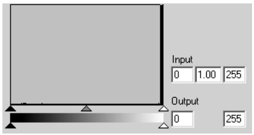
Input Level Histogram
Displaying the Histogram of Each R, G, B color
1. Click on
- When A is clicked again, the histogram of each R, G, B channel disappears.
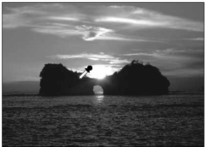
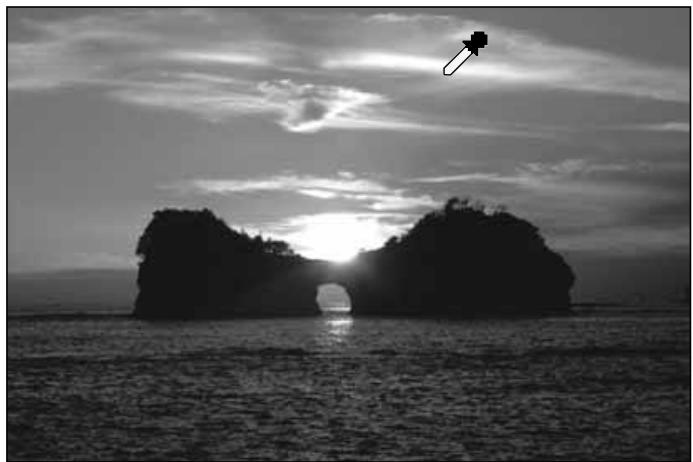
Setting the White or Black points
This function allows you to correct the highlight or shadow point to the specified value.
- Changes are automatically applied to the prescan image.
Setting the White Point
-
Double-click on
-
The Point Value Setting dialog box is displayed.
-
Input the desired white point value.
-
Click on
-
The cursor changes to the white dropper shape.
-
Click the desired highlight point of the image.
-
The image is corrected so that the point you clicked is highlight point. The color of the highlight point is the white dropper value you input in step 2.
- The change will be reflected in the prescan image.
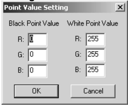
Point Value Setting dialog box
- When the film type is set to the color mode.
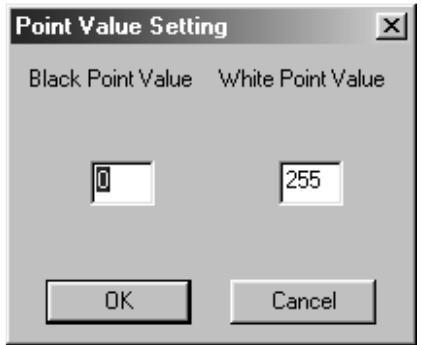
- When the film type is set to the monochrome mode.
Setting the Black point
-
Double-click on
-
The Point Value Setting dialog box is displayed.
-
Input the desired black point value.
-
Click on
-
The cursor changes to the black dropper shape.
-
Click the desired shadow point of the image.
-
The image is corrected so that the point you clicked is shadow point. The color of the shadow point is the black point value you input in step 2.
- The change will be reflected in the prescan image.
Setting the Gray point
This function can specify the point to be changed to gray in the image.
1. Click on
- The cursor changes to the gray dropper shape.
2. Click the point to be changed to gray in the image.
- The image is corrected so that the point you clicked is gray point.
- The change will be reflected in the prescan image.
NOTE:
Setting the gray point is not necessary for most images.
Viewing the Histogram of Images After Making Corrections
When is clicked, the histogram of images after making corrections can be displayed.
The histogram after making corrections is displayed as long as you press this button. When the button is released, the histogram returns to the previous one.
Auto Setting
When the Auto Setting button is clicked, the image is corrected automatically by removing no information parts from the histogram and using all tone steps from 0 to 255.
Reset
If you click the Reset button, the settings in the current correction window are reset.
When the Brightness/Contrast/Color Balance Correction button is clicked, the Brightness, Contrast and Color Balance Correction dialog box is displayed.
The images can be corrected by dragging the slider or inputting the desired value in the text box.
Click on in the Image Correction tab.
The Brightness, Contrast and Color Balance Correction Dialog box – Names of parts
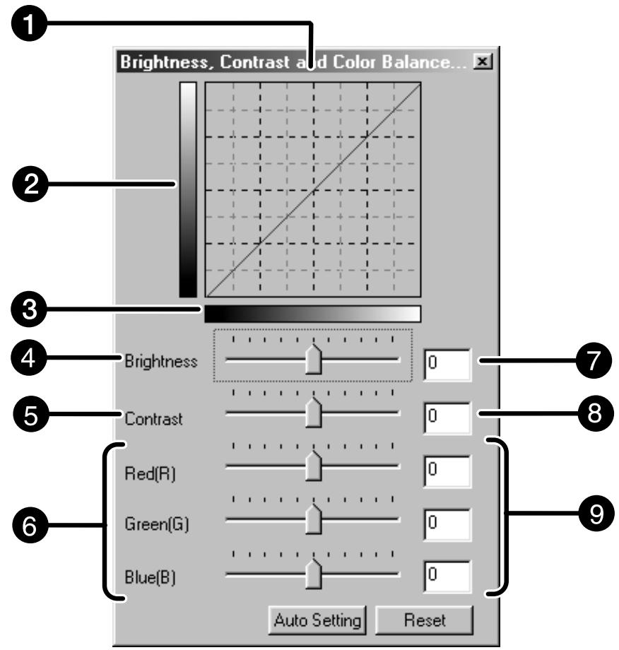
Post-Correction LUT (Look Up Table)
Post-Correction Gray scale
3 Pre-Correction Gray scale
4 Brightness slider
Contrast slider
Color Balance slider
Brightness text box
Contrast text box
Color Balance text box
1. Drag the each Brightness, Contrast or Color balance slider, or input the desired value in the text box.
- The change will be reflected in the prescan image.
- Moving the Brightness, Contrast or Color balance slider changes "Post-Correction Gray Scale" and "Post-Correction LUT".
Post-Correction LUT
The color of the image is changed as shown in the Post-Correction LUT.
The correspondence between the color displayed on the Pre-Correction Gray Scale and Post-Correction Gray Scale appears on the Post-Correction LUT.
Auto Setting
When the Auto Setting button is clicked, the brightness and contrast of the image is corrected automatically according to the lightness without changing the color balance.
Reset
If you click the Reset button, the settings in the current correction window are reset.
When the Hue/Saturation/Lightness Correction button is clicked, the Hue, Saturation, Lightness Correction dialog box is displayed.
The images can be corrected by dragging the slider or inputting the desired value in the text box.
Click on in the Image Correction tab.
The Hue, Saturation, Lightness Correction Dialog box – Names of parts
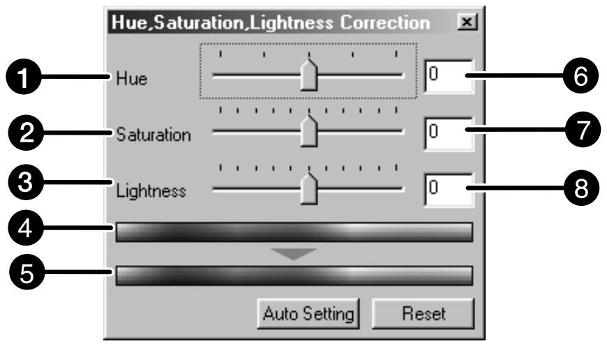
Hue-level slider
Post-Correction Color Sample
2 Saturation slider
6 Hue-level text box
3 Lightness slider
7 Saturation text box
Pre-Correction Color Sample
Lightness text box
1. Drag the each Hue, Saturation or Lightness slider, or input the desired value in the text box.
- The change will be reflected in the prescan image.
- To change the color, move the Hue, Saturation or Lightness slider (or input the desired value in the text box).
Moving the slider changes "Pre-Correction Color Sample" and "Post-Correction Color Sample".
Pre-Correction Color Sample and Post-Correction Color Sample
The color of the image is changed as shown in "Correction Color Sample". The color displayed in "Pre-Correction Color Sample" is changed as shown in "Post-Correction Color Sample".
Auto Setting
When the Auto Setting button is clicked, the saturation of the image is corrected automatically without changing the hue and lightness.
Reset
If you click the Reset button, the settings in the current correction window are reset.
The few frames of variation images are displayed around the corrected prescan image. You can correct the image while comparing with the variation images.
Click on in the Image Correction tab.
The Variation Dialog Box – Names of Parts
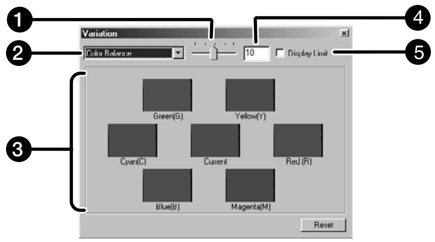
1 Variation Amount Control slider
4 Variation Amount Control text box
Correction list box
Limit Indication check box
Pre/Post Correction Image Display Area
Selecting the Correction Item
The correction item of the available variation can be selected from the color balance, brightness, contrast and saturation. However, the color balance and saturation are not available when using the monochrome film.
-
Click on the arrow next to the correction item in the correction list box. The available correction items are displayed.
-
Click the correction item.
The few frames of variation images corrected according to the selected correction item are displayed.
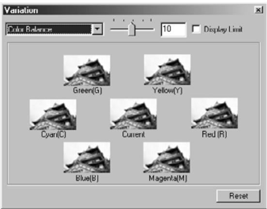
Color Balance Correction
The 6 images that have been corrected by one-step in each RGBCMY direction for the center current image are displayed.
1. Click the color balance.
- The corrected 6 frames of variation images are displayed.
2. Click the image in the direction you want to correct from the 6 frames of the variation images except for the center image.
- The image you clicked is placed in center and 6 new variation images that have been corrected by one-step in each direction.
3. Correct the image properly by repeating the operation in step 2.
Brightness & Contrast Correction
The 8 images of which brightness and contrast have been corrected by one-step in horizontal and vertical direction respectively for the center image are displayed. The variation images on the left and lower sides of the center image show the “-” correction effect, and on the right and upper sides of the center image show the “+” correction effect.
1. Click the image in the direction you want to correct from the 8 frames of the variation images except the center image.
- The image you clicked is placed in the center and 8 new frames of the prescan images that have been corrected in each direction are displayed.
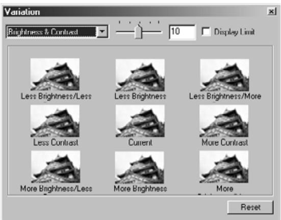
2. Correct the image properly by repeating the operation in step 1.
Saturation Correction
The 2 images of which saturation has been corrected on the right and left sides of the center image are displayed. The variation image on the left side shows reduced saturation, and on the right side shows increased saturation.
-
Click the image in the direction you want to correct from the 2 frames of the images except for the image in center.
-
The image you clicked is placed in center and 2 new frames of the variation images that have been corrected in each direction are displayed.
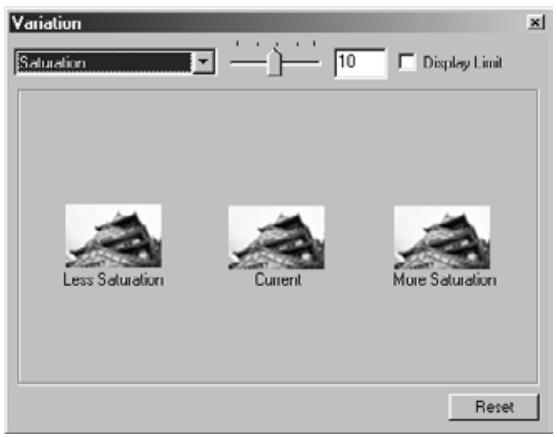
- Correct the image properly by repeating the operation in step 1.
Changing the Amount of Correction Step
The amount of correction step can be changed by moving the Variation Amount Control slider. The desired amount can also be input in the text box.
Reset
If you click the Reset button, the settings in the current correction window are reset.
When the Snapshot button is clicked, the current prescan image is stored in the Snapshot Display Area temporarily and displayed as a thumbnail.
When the thumbnail in the Snapshot Display Area is double-clicked, that image is displayed in the Prescan tab.
This is convenient when storing the image correction temporarily while processing, or when correcting the image again after going back to a certain step.
Storing in the Snapshot Display Area temporarily
1. Click on
- The displayed prescan image is displayed in the Snapshot Display Area as a temporary storing place.
Snapshot Display Area 1
Displaying the image stored temporarily as a prescan image
1. Click on the thumbnail in the Snapshot Display Area.
- The displayed prescan image is deleted and the thumbnail image is displayed as a prescan image.
Snapshot Display Area 2
Cancelling the Image Correction
When the Undo button is clicked, the current image correction is cancelled and the image returns to the previous one.
Redo the Correction
When the Redo button is clicked, the cancelled image correction can be resumed.
Delete the Image Correction
When the Correction Reset button in the Image Correction tab is clicked, all the image corrections are deleted and the image returns to the initial state.
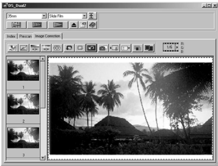
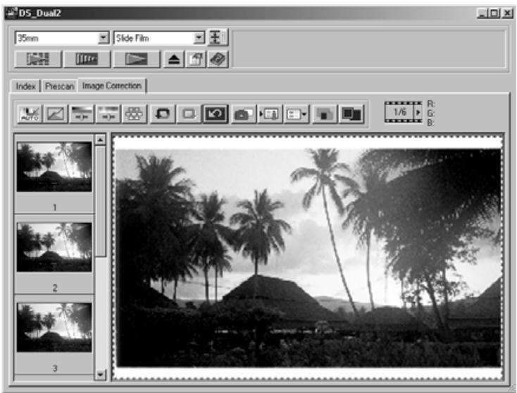
Full-Screen View
This function allows you to display a full screen view of the corrected image in the Image Correction tab.
1. Click on
- When is clicked, the size of pre and post correction image is automatically changed according to the size of the Main window.
Checking the Correction Result While Lining Up Images
When is clicked, the Image correction tab is divided into right and left sides, the pre-correction image is displayed on the left side, and post-correction image is displayed on the right side.
The image correction setting in the correction window can be saved as an image correction job. You can easily correct the image by loading the most appropriate previously saved correction job.
Saving an Image Correction Job
1. Click on in the Image correction tab.
- The Register Image Correction Job dialog box is displayed.
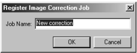
2. Input the job name and click on OK
- The current image correction setting is saved as an image correction job.
Loading Image Correction Job
This function allows you to load the saved correction job and apply an image correction to the displayed image.
1. Click on in the Image correction tab.
- The Selected Image Correction Job dialog box is displayed.
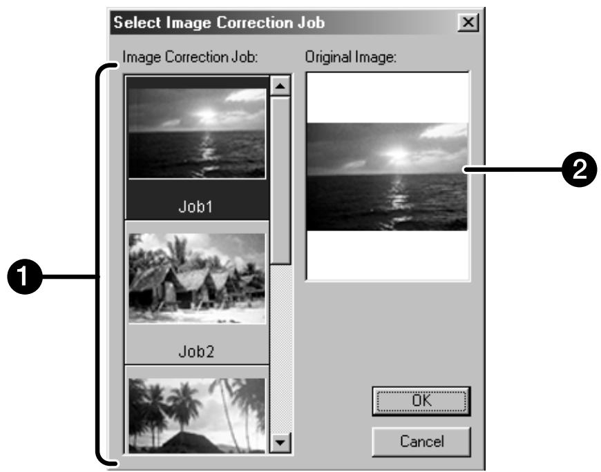
1 Image Correction job display area
Original image display
- Select the image correction job and click on OK
FINAL SCAN
FLOW
Scan setting
Creating a job
Deleting a job
Job type
Navigation
Final scan
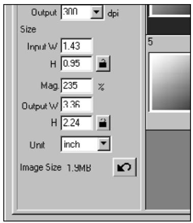
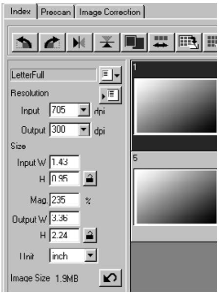
The scan settings determine your final image's resolution, dimensions, and file size, as well as helping determine the image quality. You can select a Job (see page 87) to have the scan settings selected for you or you can directly enter them into the Main window (Index tab or Prescan tab).
The Scan Settings part window – Names of parts
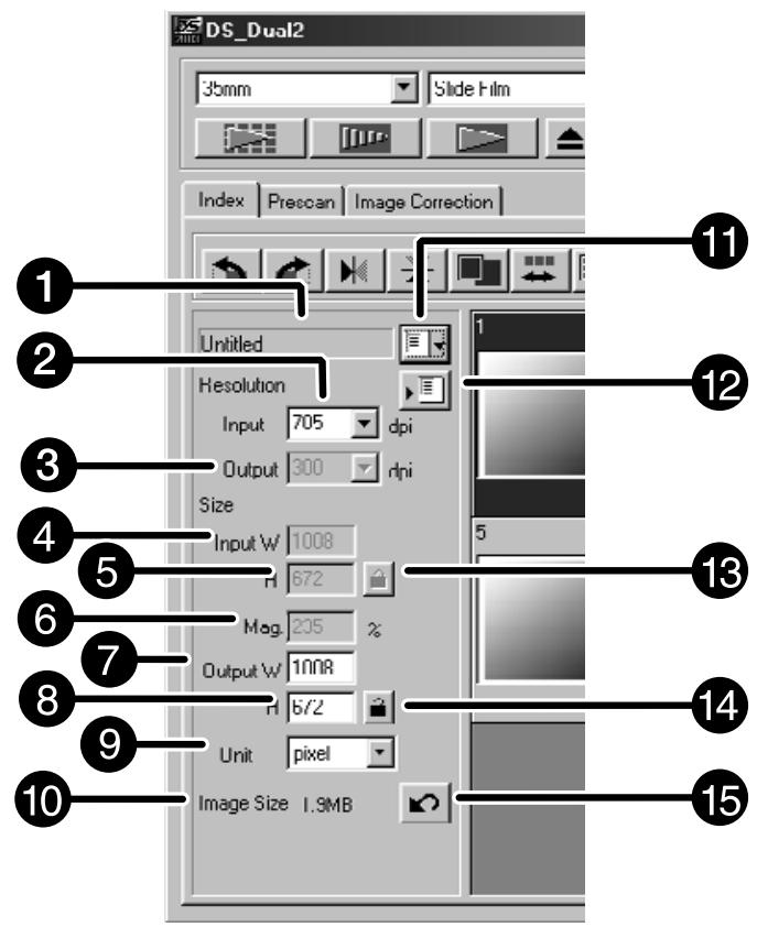
Job Name list box
2 Input Resolution list box
3 Output Resolution list box
4 Input Size text box (W)
Input Size text box (H)
Magnification Size text box
Output Size text box (W)
Output Size text box (H)
Unit list box
10 Image Size display
11 Job Load button
Job Registry button
Input size lock button
14 Output size lock button
Reset button
Image resolution is the number of pixels per inch (ppi or dpi) that represent your scanned image. The size of an image file is determined by its size (dimensions) and resolution.
The rule to follow when scanning is "bigger is better". To obtain the best results, set the output resolution to the highest value your final output device (printer, monitor, etc.) can handle. The driver software automatically determines the input resolution necessary to obtain the desired output size and resolution.
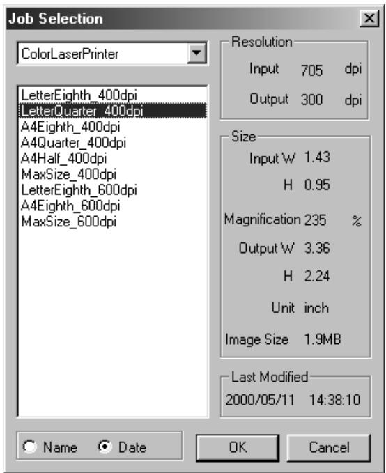
1. Click on
The Job Selection dialog box will appear.
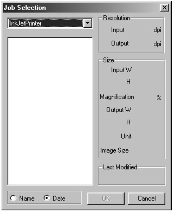
- Select the appropriate category from the drop-down list.
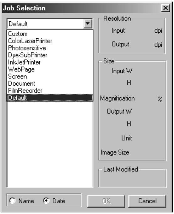
-
Click on the job file name to select it, then click on OK
-
The settings are applied to the active Prescan window.

NOTE:
Job names can be listed chronologically or alphabetically. Select the format by clicking on the Name or Date option button.
- The cropping frame changes accordingly, but can be proportionally resized.
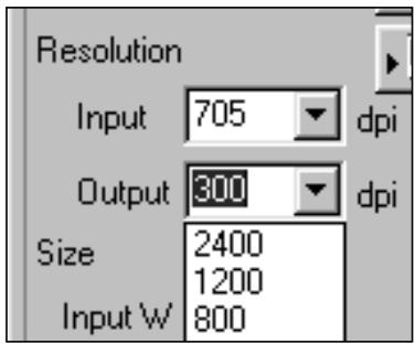
4. Enter the desired output resolution from the output resolution drop-down list.
- Values can also be entered into the output resolution list box directly.
5. The dimensions of the cropping frame are displayed in the input size text boxes.
- Values can be entered directly or by resizing the cropping frame.
- The values will change if a different unit of measure is selected.
- The scanning area size can't be changed if the Input Size is locked.
6. Enter the desired output size (maximum 3 digits).
- The output size is limited by the maximum resolution of the scanner.
- The values will change if a different unit of measure is selected.
- The output size cannot be changed when the unit list box is set to pixels.
- The scanning area size can be changed proportionally (within the resolution limits) when the Output Size is locked.
NOTE:
- Click on to lock the settings. The icon will change to . Click again to unlock.
- The magnification text box displays the output/output size ratio as a percentage.
- Magnification values can be entered directly.
7. The input scan resolution text box is set to the lowest input (scan) resolution necessary to achieve the desired output size and resolution.
- Input scan resolutions can also be selected from the drop down list or entered directly.
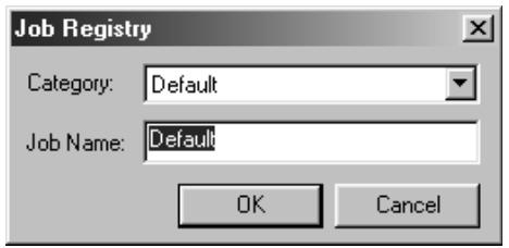
Creating a Job
In addition to the Job settings included with the software, it is possible to create and save your own Job settings.
- Set the desired settings in the Main window (Index tab or Prescan tab).
- Click on
The Job Registry dialog box will appear
- Name the job by entering a title and select the desired category, then click on OK
Deleting a Job
It is possible to delete the Job you created when it is no longer needed.
- Click on the name of the job in the Main window scan settings part, then press the delete key on your keyboard.
Before making the final scan, the scanner needs to know how big the final image will be and the quality of output that will be used (printer, monitor, etc.) so it knows what resolution to scan the film. Using the Job function is a quick and easy way to enter the scan settings.
| Scan Job Category | Description |
| Custom | User created scan settings (see page 84). |
| Color Laser Printer | Digital color copiers and color laser printersUses output resolution of 400 or 600 dpi. There are two paper-size options; letter and A4. |
| Photosensitive | Printers that use photosensitive/photographic materialCan use output resolutions of 400 dpi, 360 dpi, 267 dpi, and 180 dpi. There are ten paper size options. |
| Dye-Sub Printer | Dye-sublimation printersUses an output resolution of 300 dpi. There are 4 paper size options. |
| Ink Jet Printer | Uses an output resolution of 200 dpi. There are 4 paper size options. |
| Web Page | For use on home pagesImage size is listed in pixels and will vary. Standard Photo CD sizes are also available. |
| Screen | For monitor displayImage size is listed in pixels and will be the VGA standard of 640 x 480 pixels or larger. |
| Document | For insertion into documentsUses an output resolution of 72 dpi. Image size depends on the paper size selected. |
| Film Recorder | For high input resolution images that will be output to a film recorder. |
| Default | This category uses the default settings for the film format. The scan settings appear in the Job Selection window. |
Scan the film according to the Prescan settings.
With the Dimage Scan Dual2 utility software, you can save the final scan in one of the following file formats.
- JPEG
TIFF - BMP (Windows only)
- PICT (Macintosh operating system only)
The image file of 48 bit (16 bit each RGB) can only be saved in the tiff format.
Twain Driver/Plug-in Software
With the Prescan image displayed in the Prescan tab...
1. Click on in the Main window.
- The final scan will begin.
- When scanning is complete, the final scan will appear in the host applications window.
2. Save the image using the instructions for your host application.
3. Close the Control Window to exit the DimAge Scan Dual2 driver software.
- The driver window will close automatically after each scan if the Close Driver After Scanning option was selected in the Preferences dialog box (see page 39).
Utility Software
With the Prescan image displayed in the Prescan tab...
1. Click on in the Main window.
Your system's standard save dialog box will appear.
2. Enter the desired file name and select the file destination.
3. Select the file type from the drop-down list.
4. Click on Save
- The final scan will begin.
- When scanning is complete, the scan will be saved in the selected location. The software will return to the Prescan tab.
5. Close the Control Window to exit the DimAge Scan Dual2 driver software.
- The driver window will close automatically after each scan if the Close Driver After Scanning option was selected in the Preferences dialog box (see page 39).
The Navigation window allows you to automate the procedure of scanning. When the Navigation button is clicked in the Main window, the Navigation dialog box is displayed.
The Navigation Dialog box – Name of parts
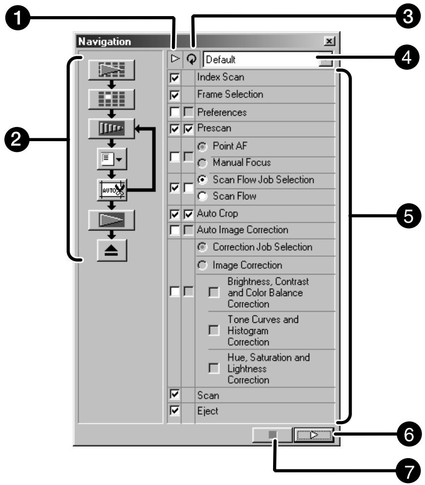
Operation Item checkbox
2 Navigation Flow
Repeated Operation Item checkbox
Navigation Menu list box
Operation Items
Navigation Start button
Navigation Stop button
Navigation Menu
This menu allows you to select the saved setting for automatic operation. Not only the saved settings but the "Save Setting" and "Delete Setting" items are displayed in this menu.
1. Select the operation items in the Operation Item checkbox or Repeated Operation Item checkbox.
- The selected items are displayed with the buttons and arrows as a Navigation Flow.
2. Click on
- To stop, click the Navigation Stop button.
Operation item checkbox
1. Insert the check mark in the operation items to be performed as part of the automatic operation.
Repeated operation item checkbox
Repeated operation items are only used when scanning a series of selected frames.
1. Insert the check mark in the operation items to be performed for all selected frames every time you execute the automatic operation.
Operation items
The operation items in the automatic operation are displayed.
1. Select the details of the operation items with the radio button or checkbox.
Saving, Selecting and Deleting a Navigation Setting
This function allows you to save the navigation settings. The above settings can be saved, selected or deleted in the Navigation Menu list box.
Saving a Navigation setting
- Click on the arrow next to the Navigation menu list to display the available menu.
- Select saving setting.
- The navigation set saving dialog box is displayed.
- Input the setting name and click the OK button.
Selecting navigation setting
- Click on the arrow next to the Navigation menu list to display the available menu.
- Select the setting to be used.
Deleting navigation setting
- Click on the arrow next to the Navigation menu list to display the available menu.
-
Select the setting to be deleted.
-
The navigation set deleting dialog box is displayed.
-
Select the setting to be deleted and click the Delete button.
APPENDIX
Color machining
Scan job file list
Glossary
Trouble shooting
Specifications
User technical support
The function allows you to match the scanner data to the monitor specification (color space). Colors in the original film are reproduced on the monitor with a high fidelity. The output color space and the monitor ICC profile can be specified with the color matching function.
To match the scanner data to the color space, specify the output color space.
To correct the color reproduction character of the monitor and to reduce the difference of color between monitors in different environments in addition to the color space setting, specify the monitor ICC profile settings in both the driver software and a software such as Photoshop. For details, refer to page 95.
1. Click on in the Main window.
The Color Matching in the Preference Dialog Box – Name of parts

Color Matching ON checkbox
Use ICC profile checkbox
3 ICC profile text box
Output Color Space list box
5 ICC profile Load button
2. Set the preferences as desired.
- De-select the Close Driver After Scanning check box when scanning multiple images at the same time.

NOTE:
When the color matching function is used, the processing time will be longer.
Output color space setting
- Insert the check mark in the "Color Matching ON" checkbox.
- Click the (menu) button in the Output Color Space list box, the available output color space settings are displayed.
- Click the desired output color space setting.
ICC profile setting
- Insert the check mark in the "Use ICC profile" checkbox.
-
Click the ICC profile Load button.
-
The standard file open dialog of your operating system is displayed.
-
Select the ICC profile according to the monitor being used.
The application may perform the original matching process. If you want to change the setting, refer to the following sample settings.
And, when the color matching function is used, the color matching function of OS, video card, etc. are set to OFF.
When using an application of which the monitor color matching function is set to ON
Output color space ^*1) :
The same color space as specified in the application is specified.
ICC profile*2):
use
When using an application of which the monitor color matching function is set to OFF, or when using an application which does not have the monitor color matching function.
Output color space: do not specify
ICC profile*2): use
When an image is scanned with this setting, the data is matched to the monitor being used.
^1) The same color space as specified in the application is specified.
2) ICC profile specifies the ICC profile of the monitor being used.
For your reference, the following is a listing of the scan job categories and names for the 35mm and APS film formats.
| Category | Job name | Resolution | Mag. | Unit | Input Size | Input Lock | Output Size | Output Lock | |||
| In | Out | W | H | W | H | ||||||
| Default | Default | 705 | 300 | 235 | pixel | 1008 | 672 | OFF | 1008 | 672 | OFF |
| Color Laser Printer | Max Size_600dpi | 2820 | 600 | 470 | mm | 36.3 | 24.2 | OFF | 170.00 | 113.00 | ON |
| A4Quarter_600dpi | 2447 | 600 | 407 | mm | 36.3 | 24.2 | OFF | 148.00 | 98.70 | ON | |
| A4Eighth_600dpi | 1735 | 600 | 289 | mm | 36.3 | 24.2 | OFF | 105.00 | 70.00 | ON | |
| Letter Quarter_600dpi | 2291 | 600 | 381 | inch | 1.43 | 0.95 | OFF | 5.46 | 3.64 | ON | |
| Letter Eighth_600dpi | 1702 | 600 | 283 | inch | 1.43 | 0.95 | OFF | 4.05 | 2.70 | ON | |
| Max Size_400dpi | 2820 | 400 | 705 | mm | 36.3 | 24.2 | OFF | 256.00 | 170.00 | ON | |
| A4Half_400dpi | 2313 | 400 | 578 | mm | 36.3 | 24.2 | OFF | 210.00 | 140.00 | ON | |
| A4Quarter_400dpi | 1629 | 400 | 407 | mm | 36.3 | 24.2 | OFF | 147.00 | 98.00 | ON | |
| A4Eighth_400dpi | 1156 | 400 | 289 | mm | 36.3 | 24.2 | OFF | 105.00 | 69.90 | ON | |
| Letter Half_400dpi | 2291 | 400 | 572 | inch | 1.42 | 0.95 | OFF | 8.19 | 5.46 | ON | |
| Letter Quarter_400dpi | 1526 | 400 | 381 | inch | 1.43 | 0.95 | OFF | 5.45 | 3.63 | ON | |
| Letter Eighth_400dpi | 1133 | 400 | 283 | inch | 1.43 | 0.95 | OFF | 4.05 | 2.70 | ON | |
| Photosensitive | Max Size | 2820 | 400 | 705 | mm | 36.3 | 24.2 | OFF | 256.00 | 170.00 | ON |
| A5_400dpi | 2313 | 400 | 578 | mm | 36.3 | 24.2 | OFF | 210.00 | 140.00 | ON | |
| 8x10_400dpi | 2798 | 400 | 699 | inch | 1.43 | 0.95 | OFF | 10.00 | 6.66 | ON | |
| 5x7_400dpi | 1961 | 400 | 490 | inch | 1.43 | 0.95 | OFF | 7.01 | 4.67 | ON | |
| PostCard4 6_400dpi | 1678 | 400 | 419 | inch | 1.43 | 0.95 | OFF | 6.00 | 4.00 | ON | |
| Letter_267dpi | 2039 | 267 | 763 | inch | 1.43 | 0.95 | OFF | 10.90 | 7.27 | ON | |
| A4_267dpi | 2187 | 267 | 819 | mm | 36.3 | 24.2 | OFF | 297.00 | 198.00 | ON | |
| A5_267dpi | 1545 | 267 | 578 | mm | 36.3 | 24.2 | OFF | 210.00 | 140.00 | ON | |
| 8x10_267dpi | 1870 | 267 | 700 | inch | 1.43 | 0.95 | OFF | 10.00 | 6.67 | ON | |
| 5x7_267dpi | 1307 | 267 | 489 | inch | 1.43 | 0.95 | OFF | 7.00 | 4.66 | ON | |
| PostCard4 6_267dpi | 1120 | 267 | 419 | inch | 1.43 | 0.95 | OFF | 6.00 | 4.00 | ON | |
| (unavailable) | 1597 | 360 | 443 | mm | 36.3 | 24.2 | OFF | 161.00 | 107.00 | ON | |
| 2L_360dpi | 1727 | 360 | 479 | mm | 36.3 | 24.2 | OFF | 174.00 | 116.00 | ON | |
| 14x17_180dpi | 2123 | 180 | 1179 | mm | 36.3 | 24.2 | OFF | 428.00 | 285.00 | ON | |
| 11x14_180dpi | 1747 | 180 | 970 | mm | 36.3 | 24.2 | OFF | 352.00 | 235.00 | ON | |
| 10x12_180dpi | 1494 | 180 | 830 | mm | 36.3 | 24.2 | OFF | 301.00 | 200.00 | ON | |
| (unavailable) | 797 | 180 | 442 | mm | 36.3 | 24.2 | OFF | 160.00 | 106.00 | ON | |
| 2L_180dpi | 857 | 180 | 476 | mm | 36.3 | 24.2 | OFF | 173.00 | 115.00 | ON | |
| Dye-Sub Printer | A4Full | 2455 | 300 | 818 | mm | 36.3 | 24.2 | OFF | 297.00 | 198.00 | ON |
| A4Half | 1735 | 300 | 578 | mm | 36.3 | 24.2 | OFF | 210.00 | 140.00 | ON | |
| A4Quarter | 1223 | 300 | 407 | mm | 36.3 | 24.2 | OFF | 148.00 | 98.70 | ON | |
| A4Eighth | 866 | 300 | 289 | mm | 36.3 | 24.2 | OFF | 104.00 | 69.90 | ON | |
| Letter Full | 2291 | 300 | 763 | inch | 1.43 | 0.95 | OFF | 10.90 | 7.28 | ON | |
| Letter Half | 1714 | 300 | 571 | inch | 1.43 | 0.95 | OFF | 8.17 | 5.44 | ON | |
| Letter Quarter | 1144 | 300 | 381 | inch | 1.43 | 0.95 | OFF | 5.45 | 3.63 | ON | |
| Letter Eighth | 850 | 300 | 283 | inch | 1.43 | 0.95 | OFF | 4.05 | 2.70 | ON | |
| (unavailable) | 1223 | 300 | 407 | mm | 36.3 | 24.2 | OFF | 148.00 | 98.70 | ON | |
| Photo4x6 | 1240 | 300 | 413 | mm | 36.3 | 24.2 | OFF | 150.00 | 100.00 | ON | |
| Photo3x5 /Photo9x13 | 1049 | 300 | 349 | mm | 36.3 | 24.2 | OFF | 127.00 | 84.60 | ON | |
| Ink-Jet Printer | A4Full | 163 | 200 | 818 | mm | 36.3 | 24.2 | OFF | 297.00 | 198.00 | ON |
| A4Half | 1156 | 200 | 578 | mm | 36.3 | 24.2 | OFF | 210.00 | 139.00 | ON | |
| A4Quarter | 814 | 200 | 407 | mm | 36.3 | 24.2 | OFF | 148.00 | 98.50 | ON | |
| A4Eighth | 577 | 200 | 288 | mm | 36.4 | 24.3 | OFF | 105.00 | 69.80 | ON | |
| Letter Full | 1526 | 200 | 763 | inch | 1.42 | 0.95 | OFF | 10.90 | 7.27 | ON | |
| Letter Half | 1144 | 200 | 572 | inch | 1.42 | 0.95 | OFF | 8.17 | 5.45 | ON | |
| Letter Quarter | 763 | 200 | 381 | inch | 1.43 | 0.95 | OFF | 5.45 | 3.63 | ON | |
| Letter Eighth | 566 | 200 | 283 | inch | 1.43 | 0.95 | OFF | 4.05 | 2.70 | ON | |
| (unavailable) | 814 | 200 | 407 | mm | 36.3 | 24.2 | OFF | 148.00 | 98.50 | ON | |
| Photo4x6 | 826 | 200 | 413 | mm | 36.3 | 24.2 | OFF | 150.00 | 100.00 | ON | |
| Photo3x5 /Photo9x13 | 699 | 200 | 349 | mm | 36.3 | 24.0 | OFF | 127.00 | 84.50 | ON | |
| Category | Job Name | Resolution | Input Size | Output Size | |||||||
| In | Out | Mag. | Unit | W | H | Lock | W | H | Lock | ||
| Web Page | 1023 x 682 | 716 | 300 | 238 | pixel | 1023 | 682 | OFF | 1023 | 682 | ON |
| 960 x 640 | 671 | 300 | 223 | pixel | 960 | 640 | OFF | 960 | 640 | ON | |
| 870 x 580 | 608 | 300 | 202 | pixel | 870 | 580 | OFF | 870 | 580 | ON | |
| 768 x 512 | 537 | 300 | 179 | pixel | 768 | 512 | OFF | 768 | 512 | ON | |
| 624 x 416 | 436 | 300 | 145 | pixel | 624 | 416 | OFF | 624 | 416 | ON | |
| 600 x 400 | 419 | 300 | 139 | pixel | 600 | 400 | OFF | 600 | 400 | ON | |
| 480 x 320 | 335 | 300 | 111 | pixel | 480 | 320 | OFF | 480 | 320 | ON | |
| Photo CD 2048 x 3072 | 2148 | 300 | 716 | pixel | 3072 | 2048 | OFF | 3072 | 2048 | ON | |
| Photo CD 1024 x 1536 | 1074 | 300 | 358 | pixel | 1536 | 1024 | OFF | 1536 | 1024 | ON | |
| Photo CD512 x 768 | 537 | 300 | 179 | pixel | 768 | 512 | OFF | 768 | 512 | ON | |
| Photo CD256 x 348 | 243 | 300 | 81 | pixel | 348 | 232 | OFF | 348 | 232 | ON | |
| Screen | 1280 x 1024 | 895 | 300 | 298 | pixel | 1280 | 853 | OFF | 1280 | 853 | ON |
| 1280 x 960 | 895 | 300 | 298 | pixel | 1280 | 853 | OFF | 1280 | 853 | ON | |
| 1152 x 870 | 805 | 300 | 268 | pixel | 1152 | 768 | OFF | 1152 | 768 | ON | |
| 1024 x 768 | 716 | 300 | 238 | pixel | 1024 | 682 | OFF | 1024 | 682 | ON | |
| 832 x 624 | 582 | 300 | 194 | pixel | 832 | 554 | OFF | 832 | 554 | ON | |
| 800 x 600 | 559 | 300 | 186 | pixel | 800 | 533 | OFF | 800 | 533 | ON | |
| 640 x 480 | 47 | 300 | 149 | pixel | 640 | 426 | OFF | 640 | 426 | ON | |
| Document | A4 Half | 416 | 72 | 577 | mm | 36.3 | 24.2 | OFF | 210.00 | 139.00 | ON |
| A4 Quarter | 293 | 72 | 406 | mm | 36.4 | 24.1 | OFF | 148.00 | 98.40 | ON | |
| A4 Eighth | 207 | 72 | 287 | mm | 36.4 | 24.3 | OFF | 105.00 | 70.00 | ON | |
| Letter Half | 411 | 72 | 570 | inch | 1.43 | 0.95 | OFF | 8.16 | 5.44 | ON | |
| Letter Quarter | 274 | 72 | 379 | inch | 1.43 | 0.95 | OFF | 5.44 | 3.62 | ON | |
| Letter Eighth | 203 | 72 | 281 | inch | 1.44 | 0.96 | OFF | 4.04 | 2.69 | ON | |
| Film Recorder | 35mm Full-Frame | 2382 | 2400 | 99 | mm | 36.30 | 24.20 | OFF | 36.00 | 24.00 | ON |
| 35mm Half-Frame | 1586 | 2400 | 66 | mm | 36.30 | 24.20 | OFF | 24.00 | 16.00 | ON | |
| 35mm Quarter-Frame | 1189 | 2400 | 49 | mm | 36.7 | 24.40 | OFF | 18.00 | 11.90 | ON | |
| Category | Job name | Resolution | Mag. | Unit | Input Size | Input Lock | Output Size | Output Lock | |||
| In | Out | W | H | W | H | ||||||
| Default | Default | 705 | 300 | 235 | pixel | 832 | 480 | OFF | 832 | 480 | OFF |
| Color Laser Printer | Max Size_600dpi | 2820 | 600 | 470 | mm | 29.9 | 17.2 | OFF | 140.00 | 81.20 | ON |
| A4 Eighth_600dpi | 2104 | 600 | 350 | mm | 30.0 | 17.3 | OFF | 105.00 | 60.60 | ON | |
| Letter Eighth_600dpi | 2161 | 600 | 360 | inch | 1.18 | 0.68 | OFF | 4.25 | 2.45 | ON | |
| Max Size_400dpi | 2820 | 400 | 705 | mm | 29.9 | 17.2 | OFF | 211.00 | 121.00 | ON | |
| A4 Half_400dpi | 2809 | 400 | 702 | mm | 29.9 | 17.2 | OFF | 210.00 | 121.00 | ON | |
| A4 Quarter_400dpi | 1977 | 400 | 494 | mm | 30.0 | 17.3 | OFF | 148.00 | 85.40 | ON | |
| A4 Eighth_400dpi | 1401 | 400 | 350 | mm | 30.0 | 17.3 | OFF | 105.00 | 60.60 | ON | |
| Letter Quarter_400dpi | 1851 | 400 | 462 | inch | 1.18 | 0.68 | OFF | 5.46 | 3.15 | ON | |
| Letter Eighth_400dpi | 1440 | 400 | 360 | inch | 1.18 | 0.68 | OFF | 4.25 | 2.45 | ON | |
| Photosensitive | Max Size | 2820 | 400 | 705 | mm | 29.9 | 17.2 | OFF | 211.00 | 121.00 | ON |
| A5_400dpi | 2809 | 400 | 702 | mm | 29.9 | 17.2 | OFF | 210.00 | 121.00 | ON | |
| 5x7_400dpi | 2374 | 400 | 593 | inch | 1.18 | 0.68 | OFF | 7.00 | 4.04 | ON | |
| Post Card 4 x 6_400dpi | 2039 | 400 | 509 | inch | 1.18 | 0.68 | OFF | 6.01 | 3.47 | ON | |
| Letter_267dpi | 2472 | 267 | 925 | inch | 1.18 | 0.68 | OFF | 10.90 | 6.30 | ON | |
| A4_267dpi | 2654 | 267 | 994 | mm | 29.9 | 17.2 | OFF | 297.00 | 171.00 | ON | |
| A5_267dpi | 1870 | 267 | 700 | mm | 30.0 | 17.2 | OFF | 210.00 | 121.00 | ON | |
| 8x10_267dpi | 2263 | 267 | 847 | inch | 1.18 | 0.68 | OFF | 10.00 | 5.76 | ON | |
| 5x7_267dpi | 1586 | 267 | 594 | inch | 1.17 | 0.68 | OFF | 7.00 | 4.04 | ON | |
| PostCard4 x 6_267dpi | 1359 | 267 | 508 | inch | 1.18 | 0.68 | OFF | 6.00 | 3.46 | ON | |
| (unavailable) | 1935 | 360 | 537 | mm | 30.0 | 17.3 | OFF | 161.00 | 92.90 | ON | |
| 2L_360dpi | 2092 | 360 | 581 | mm | 29.9 | 17.2 | OFF | 174.00 | 100.00 | ON | |
| 14x17_180dpi | 2578 | 180 | 1432 | mm | 29.9 | 17.2 | OFF | 429.00 | 247.00 | ON | |
| 11x14_180dpi | 2117 | 180 | 1176 | mm | 29.9 | 17.2 | OFF | 352.00 | 203.00 | ON | |
| 10x12_180dpi | 1809 | 180 | 1005 | mm | 29.9 | 17.2 | OFF | 301.00 | 173.00 | ON | |
| (unavailable) | 966 | 180 | 536 | mm | 30.0 | 17.2 | OFF | 160.00 | 92.70 | ON | |
| 2L_180dpi | 1046 | 180 | 581 | mm | 29.9 | 17.2 | OFF | 174.00 | 100.00 | ON | |
| Dye-Sub Printer | Max Size | 2820 | 300 | 940 | mm | 29.9 | 17.2 | OFF | 281.00 | 162.00 | ON |
| A4 Half | 2104 | 300 | 701 | mm | 29.9 | 17.3 | OFF | 210.00 | 121.00 | ON | |
| A4 Quarter | 1482 | 300 | 494 | mm | 29.9 | 17.2 | OFF | 148.00 | 85.40 | ON | |
| A4 Eighth | 1050 | 300 | 350 | mm | 30.0 | 17.3 | OFF | 105.00 | 60.50 | ON | |
| Letter Full | 2776 | 300 | 925 | inch | 1.18 | 0.68 | OFF | 10.90 | 6.30 | ON | |
| Letter Half | 2161 | 300 | 720 | inch | 1.18 | 0.68 | OFF | 8.50 | 4.90 | ON | |
| Letter Quarter | 1385 | 300 | 461 | inch | 1.18 | 0.68 | OFF | 5.45 | 3.14 | ON | |
| Letter Eighth | 1080 | 300 | 360 | inch | 1.18 | 0.68 | OFF | 4.25 | 2.45 | ON | |
| (unavailable) | 1500 | 300 | 500 | mm | 30.0 | 17.2 | OFF | 150.00 | 86.40 | ON | |
| Photo 9x13 | 1270 | 300 | 423 | mm | 30.0 | 17.2 | OFF | 127.00 | 73.00 | ON | |
| Ink-Jet Printer | A4 Full | 1977 | 200 | 988 | mm | 30.0 | 17.3 | OFF | 297.00 | 171.00 | ON |
| A4 Half | 1401 | 200 | 700 | mm | 30.0 | 17.3 | OFF | 210.00 | 121.00 | ON | |
| A4 Quarter | 987 | 200 | 493 | mm | 30.0 | 17.3 | OFF | 148.00 | 85.30 | ON | |
| A4 Eighth | 700 | 200 | 350 | mm | 30.0 | 17.3 | OFF | 105.00 | 60.40 | ON | |
| Letter Full | 1846 | 200 | 923 | inch | 1.18 | 0.68 | OFF | 10.90 | 6.28 | ON | |
| Letter Half | 1440 | 200 | 720 | inch | 1.18 | 0.68 | OFF | 8.50 | 4.90 | ON | |
| Letter Quarter | 924 | 200 | 462 | inch | 1.17 | 0.68 | OFF | 5.45 | 3.14 | ON | |
| Letter Eighth | 720 | 200 | 360 | inch | 1.18 | 0.68 | OFF | 4.25 | 2.45 | ON | |
| Photo 4 x 6 | 1001 | 200 | 500 | mm | 30.0 | 17.3 | OFF | 150.00 | 86.40 | ON | |
| Photo 3.5 x 5/Photo 9 x 13 | 846 | 200 | 423 | mm | 30.0 | 17.2 | OFF | 127.00 | 73.00 | ON | |
| Web Page | 1280 x 739 | 1085 | 300 | 361 | pixel | 1280 | 739 | OFF | 1280 | 739 | ON |
| 1152 x 665 | 976 | 300 | 665 | pixel | 1152 | 665 | OFF | 1152 | 665 | ON | |
| 1024 x 590 | 867 | 300 | 239 | pixel | 1024 | 590 | OFF | 1024 | 590 | ON | |
| 832 x 480 | 705 | 300 | 235 | pixel | 832 | 480 | OFF | 832 | 480 | ON | |
| 800 x 461 | 678 | 300 | 226 | pixel | 800 | 461 | OFF | 800 | 461 | ON | |
| 640 x 369 | 542 | 300 | 180 | pixel | 640 | 369 | OFF | 640 | 369 | ON | |
| Photo CD1024 x 1536 | 1303 | 300 | 434 | pixel | 1536 | 887 | OFF | 1536 | 887 | ON | |
| Photo CD512 x 768 | 650 | 300 | 216 | pixel | 768 | 443 | OFF | 768 | 443 | ON | |
| Photo CD256 x 348 | 294 | 300 | 98 | pixel | 348 | 200 | OFF | 348 | 200 | ON | |
| Screen | 1280 x 1024 | 1085 | 300 | 361 | pixel | 1280 | 739 | OFF | 1280 | 739 | ON |
| 1280 x 960 | 1085 | 300 | 361 | pixel | 1280 | 739 | OFF | 1280 | 739 | ON | |
| 1152 x 870 | 976 | 300 | 325 | pixel | 1152 | 665 | OFF | 1152 | 665 | ON | |
| 1024 x 768 | 867 | 300 | 289 | pixel | 1024 | 590 | OFF | 1024 | 590 | ON | |
| 832 x 624 | 705 | 300 | 235 | pixel | 832 | 480 | OFF | 832 | 480 | ON | |
| 800 x 600 | 678 | 300 | 226 | pixel | 800 | 461 | OFF | 800 | 461 | ON | |
| 640 x 480 | 542 | 300 | 369 | pixel | 640 | 369 | OFF | 640 | 369 | ON | |
| Document | A4 Half | 504 | 72 | 700 | mm | 30.0 | 17.3 | OFF | 210.00 | 121.00 | ON |
| A4 Quarter | 355 | 72 | 493 | mm | 30.0 | 17.3 | OFF | 148.00 | 85.00 | ON | |
| A4 Eighth | 251 | 72 | 348 | mm | 30.0 | 17.3 | OFF | 105.00 | 60.30 | ON | |
| Letter Half | 518 | 72 | 719 | inch | 1.18 | 0.68 | OFF | 8.50 | 4.90 | ON | |
| BRIGHTNESS | The lightness or darkness of the image. |
| CHANNEL | The component of an image. Your scanned image has three channels: red, green, and blue (RGB). |
| CONTRAST | The gradation of shades in an image. A high contrast image has very dark areas and bright areas without many middle shades. A low contrast image has many tones that are close to the same brightness. Low contrast images are often described as looking 'flat'. |
| CROP | To trim and delete the unwanted edges of the image. |
| DPI | Dots (pixels) per inch. |
| EMULSION SIDE | The side of the film coated with the photographic material. |
| GAMMA | The contrast of only the middle tones. |
| HIGHLIGHTS | The lighter areas of the image. |
| HISTOGRAM | A graph showing the amount of each level of the 256 brightness levels. |
| INTERPOLATION | A form of adding new pixels in an image when resampling up. |
| JPEG | The JPEG (Joint Photographic Experts Group) compression standard is capable of producing a high compression ratio while maintaining image quality. JPEG is a widely supported image file format. |
| MIDTONE | The middle shades of an image, in between light and dark. |
| NEUTRAL | Having no color cast, such as black, white, or gray. |
| PICT | (Macintosh operating system only) The PICT graphic file format uses a lossless compression scheme and is compatible with many Macintosh applications. |
| PIXEL | Abbreviation for picture element. The dots that make up an electronic image. |
| RESAMPLE | To change the number of pixels in the image. If pixels are discarded when shrinking an image, it is called resampling down. If new pixels are created in an image, it is called resampling up (see page 100). |
| RESOLUTION | The number of pixels in a given area of the image; such as pixels per inch or pixels per centimeter. High resolution is the term for an image with a lot of pixels in a given area. Low resolution means there are not many pixels in a given area. |
| RGB | Red, Green, and Blue. These are the colors of the three channels that make up the scanned image. Monitors use red, green, and blue phosphors to create the image you see on the screen. |
| SHADOWS | The dark areas of an image. |
| TIFF | Tagged Image File Format (TIFF) files contain bit-mapped data. In addition to being a widely supported format, TIFF is able to handle the color palette needed for professional-quality images and graphics. |
| USB | In the USB connection, the peripheral devices such as a mouse, printer, scanner, etc. can be connected up to 127 with an interface. Furthermore, the peripheral equipment can be easily set up because the USB connection does not require to specify the ID number or the terminator for each equipment compared with the SCSI devices. It does not matter whether the USB equipment or computer is turned on or off first. In the USB connection, the USB equipment or computer can be connected or disconnected even while the equipment is turned on. When disconnecting and connecting the USB equipment, perform at an interval of 5 seconds or more. |
| WINDOWS® BMP | (Windows only) The BMP graphic file format is for bit-mapped images. BMP images are supported by the Paint accessory and can easily be opened on most PCs running Windows. |
SYMPTOM orMESSAGE
SOLUTION
| The computer will not start up after connecting the scanner. | •Shut down the computer and all the devices in your USB chain, then check the USB cables and AC power adapter cord. |
| DS_Dual2 does not appear in the Import drop down list. | •Make sure the plug-in module has been placed in the correct folder. See page 21. |
| “Could not establish connection with scanner.” | •Indicator lamp is off - Turn the Dimâge Scan Dual2 on, then restart your system. |
| “Setting up now. Remove the film holder.” | •Remove the film holder and click on OK. |
| Indicator lamp blinking rapidly (8Hz). | •Scanner door opened during setup. Close scanner door. |
| “Set film properly...” | •Load film into the film holder. |
| “Set 35mm film holder properly.” | •Set the correct film type. |
| “Set APS film holder properly.” | •Set the correct film type. |
| “Could not recognise the film type.” | •Set the film type manually. |
| “Insufficient Memory” | •Increase the memory requirements for the host application. •If you have scanned multiple images, close and relaunch the host application. |
| “Setting up now. Remove the film holder.” appears when the film holder is not loaded. | •Contact a Minolta Service Facility to change the fluorescent lamp. |
Type: Fixed sensor, film transport, single pass
Usable Film: 35mm – negative/positive, color/B&W
APS cassette (with optional adapter) – color/B&W, negative/positive
Scanning Dimensions: 35mm - 24.2 x 36.3mm (2688 x 4032 pixels)
APS -17.28 x 29.95mm (1920 x 3328 pixels)
Optical Input Resolution: 2820 dpi
A/D Conversion: 12 bit
Image Sensor: RGB 3-line CCD (2700 pixels)
Scan Times (approx):
| Windows | 35mm | APS |
| Prescan | 10 sec. | 11 sec. |
| Scan | 60 sec. | 5 sec. |
| Index Scan | 10 sec/frame | 10 sec/frame |
Testing Conditions
IBM PC/AT
CPU: Pentium III 600MHz; RAM: 256MB;
OS: Windows 98 2nd edition; Software: Twain_32 Source;
Host Application: Adobe Photoshop 5.5; ASP version: 4.57
Interface: USB
Light Source:
3 Wavelength Cold Cathode Fluorescent
Power/Frequency:
Using the AC power adapter:
Product for North America: 100-120 volts AC, 50/60 Hz
Product for Europe: 220-240 volts AC, 50/60 Hz
Use only within the voltage range specified on the AC power Adapter.
Power Consumption: Max. 30W
Dimensions (W x H x D): 150 x 100 x 320mm
Weight (approx): 1.5kg
Specifications are based on the latest information available at the time of printing and are subject to change without notice.
Please contact your dealer for information regarding installation, USB interface recommendations, or application compatibility. If your dealer is unable to help you, contact an authorized Minolta service center.
Please have the following information ready when calling Minolta Technical Support.
Make and Model of your computer:
Available application RAM:
Operating System version:
Other connected USB devices:
DS Dual2 driver version number:
Symptoms:
Messages that appear on the screen when the problem occurs:
Frequency of occurrence:
Determining the version number of your driver software:
Place the pointer on the status window in the command window to display the version number.
When the "Add New Hardware Wizard" window is displayed
The "Add New Hardware Wizard" window may be displayed in the following cases:
- If you connected the Dimâge Scan Dual II to the PC before installing the Dimâge Scan Dual II driver software.
- If you connected the Dimâge Scan Dual II to the PC after installing the Dimâge Scan Dual II driver software. (for some PCs)
- If you performed from step 1 to 10 described on "When the Dimâge Scan Dual II driver software does not start up".
When the PC does not recognize the Dimâge Scan Dual II
When the "Add New Hardware Wizard" window is displayed, perform the following operation so that the PC recognizes the Dimâge Scan Dual II.
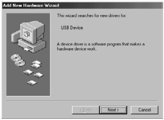
- When the "Add New Hardware Wizard" window is displayed, click on [Next>].
The window for selecting the way to search for new drivers is displayed.

- Make sure that the check mark is put on "Search for the best driver for your device. (Recommended)" and then click on [Next>].
The window for specifying the location to search is displayed.
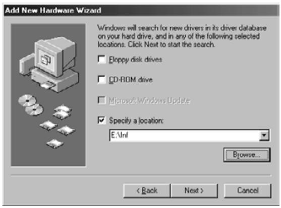
- Insert the Dimâge Scan Dual II CD-ROM into the CD-ROM drive, put the check mark on “Specify a location” and then enter “E:\inf”. (When the CD-ROM drive is the E drive.)
Note
The name of the CD-ROM drive differs depending on the setting in the preferences.
- Click on [Next>].
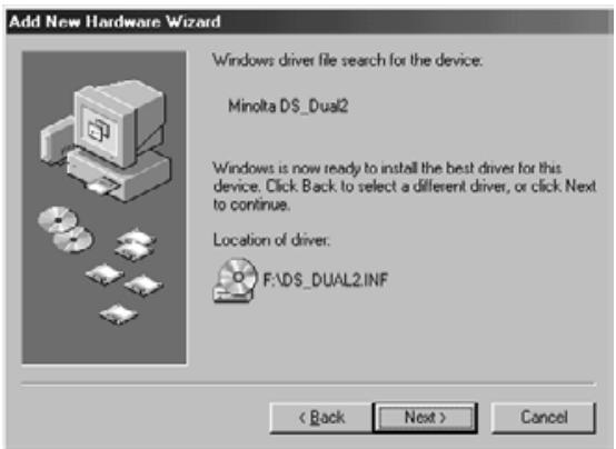
- Click on [Next>].
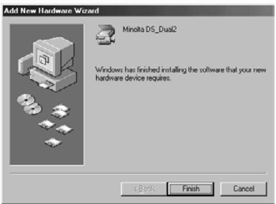
- Click on [Finish].
When the Dimâge Scan Dual II driver software does not start up
In the following cases, "Dimâge Scan Dual II is not connected." appears and the Dimâge Scan Dual II driver software may not be able to start up even if you attempt to make the Dimâge Scan Dual II start up.
The power of the Dimâge Scan Dual II is not turned on
Make sure that the power of the Dimage Scan Dual II is turned on and the power cord and the AC power adapter is connected correctly.
The Dimâge Scan Dual II is not connected to the PC correctly
Make sure that the Dimage Scan Dual II is connected to the PC correctly.
"Dimâge Scan Dual II" does not appear in the Device Manager
When the Dimêge Scan Dual II is displayed as “Unknown Device or “USB Device”, perform the following procedure so that the PC recognizes the Dimêge Scan Dual II again.

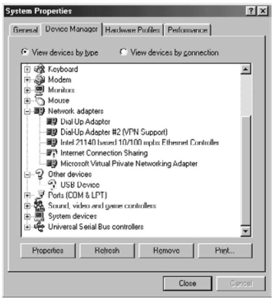
-
Click on [Remove].
-
Connect the Dimâge Scan Dual II to the PC and turn on the power of the Dimâge Scan Dual II and the PC.
- Click on "My Computer" on the desk top using the right button of the mouse and then click on "Properties".
- Click on the tab of "Device Manager".
- Make sure that "USB Device" or "Unknown Device" appears in "Other devices" as displayed left.
- Click on "USB Device" or "Unknown Device".
The "Confirm Device Removal" window is displayed.
- Click on [OK].
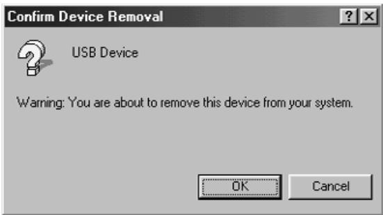
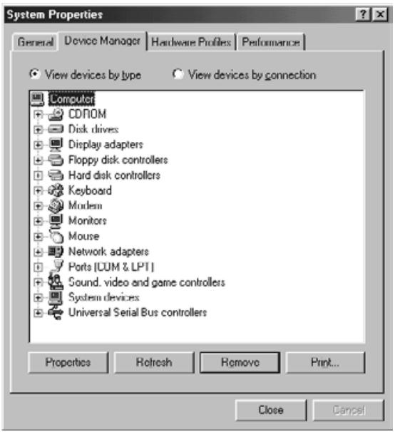
- Make sure that neither "USB Device" nor "Unknown Device" appears as displayed left and then click on [Close].
- Press the power button of the Dimâge Scan Dual II to turn off.
- Press the power button of the Dimâge Scan Dual II again to turn on.
The "Add New Hardware Wizard" window is displayed.
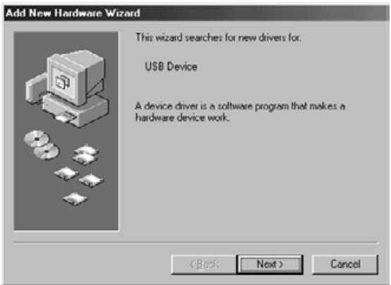
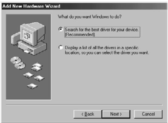
- Make the PC recognize the Dimâge Scan Dual II by following the procedure described on “When the “Add New Hardware Wizard” window is displayed”.
When using the TWAIN_32 driver with Adobe Photoshop LE (supplied with this scanner), scanning may stop halfway through the scan depending on the memory allocations to Photoshop. In this case, change the memory allocations after closing the driver software by following the procedure described below:
Switch off the scanner.
The driver software can now be closed
Close the driver software.
Select [Memory & Image Cache...] from [Preferences] in [File] menu of Photoshop
The Preferences window will appear.
Change the value* in the box of “Used by Photoshop:” in “Physical Memory Usage” and click on [OK].
*Specify the value from about 20 to 50 (%)
Close Photoshop and then restart it.
Turn on the power of the scanner again, remove the film holder and close the scanner front for set-up.
Restart the Twain_32 driver from Adobe Photoshop LE.
Perform the scanning operation again.
The memory allocations differ according to your system. If the scanning operation still cannot be performed properly even after changing the setting, change the value of the memory allocations again by following the procedure described above.
For the operations of Adobe Photoshop LE (supplied with this scanner) and Adobe Photoshop, please refer to the web site, etc. of Adobe Systems Incorporated.
A Minolta Austria Ges.m.b.H Amalienstr.59-61,A-1131 Wien,Österreich Tel:0187868176 Fax:01 87868 153 http://www.minoltaeurope.com
B Minolta Belgium Branch Prins Boudewijnlaan 1 B-2550 Kontich, Belgie Tel:034510700 Fax:034585048 http://www.minolta.be en http://www.minolta.nl
CAN Minolta Canada Inc., Head Office 369 Britannia Road East, Mississauga, Ontario L4Z 2H5, Canada Tel. 0905 890 66 00 Fax 0905 890 71 99 http://www.minolta.com
CH Minolta (Schweiz) AG
Riedstr. 6, CH-8953 Dietikon, Schweiz
Tel: 157 57 11 (sFr 2.15/min)
Fax: 01 741 33 12
http://www.minolta.ch
- Dimage Scan Dual II AF-2820U
- WARNING
- To avoid fire or electric shock:
- Improper use of the AC power adapter cord may result in fire or electric shock.
- This product must have sufficient ventilation while in use. Restricted ventilation ducts may cause the unit to overheat, increasing the risk of fire.
- CAUTION
- The following contents should be included in this package
- Software Registration
- Overview
- Scanner setup
- Easy Scan Utility
- Index Scan
- Preview scan
- Image correction
- Final scan
- Appendix
- SCANNER SETUP FLOW
- CAUTION – Before installing
- Installing Photoshop LE – Windows®98/2000
- Installing Photoshop LE -- Macintosh
- WINDOWS 98/WINDOWS 2000
- Windows 98
- Click on Next.
- Select the install drive (or folder) and type from the pulldown menus.
- Click on Install
- Click on Quit
- Drag the DS Dual2 Plug-in to the Import/Export folder in the Adobe Photoshop Plug-ins folder.
- NOTE:
- EASY SCAN UTILITY FLOW
- Starting up the utility software
- After performing steps 1 and 2 on page 36, select Start > Program (P) > Minolta Dimâge Scan Dual2 ver.1.0 > EasyScan.
- MACINTOSH
- After performing steps 1 and 2 on page 36, double-click on the Dimâge Scan Dual2 ver. 1.0 folder and then double-click on EasyScan.
- Easy Scan Utility Window
- The Easy Scan Utility Window – Name of parts
- Loading the 35 mm Negative Film Holder – FH-U1
- Loading the Slide Mount Holder - SH-U1
- Names of Parts
- Loading the APS Adapter
- Scanning with the FH-U1 35 mm film or SH-U1 slide film holder
- Selecting the film type
- Select whether the index scan should be perform or not.
- Setting the usage
- Rotate
- Click on the Scan button to scan.
- SCANNING FLOW
- Launching the TWAIN Driver – Windows
- Launching the Plug-in – Macintosh
- Launching the Utility Software
- Windows
- Click on in the Command window.
- The Preference Dialog Box – Name of parts
- Set the preferences as desired.
- Index Scan priority
- When scanning APS, set the Preferences as desired in the APS settings part.
- Auto film rewind
- Rotate All Frames 180 Degrees
- Click on OK to accept the new preference settings.
- Changing the Window Size
- Selecting Frames
- Click on an image to select it for scanning.
- Click on to scan the selected image (s).
- Refer to page 46 to save the scanned image(s).
- Rotating the Index Frames
- Reversing Frame order
- Click on the 'Save Index Image' button in the Main window.
- [Windows®]
- [Macintosh]
- Enter the desired file name, select the file destination and then click on Save.
- Click on the 'Save Index' button in the Main window.
- Click on the 'Read Saved Index' button in the Main window.
- Select the index file to be read and then click on OK.
- Flip
- Full screen view
- Click on
- Magnifying or Reducing the View
- Zooming In
- Click on Q .
- Click anywhere on the image to zoom in.
- Zooming Out
- Press and hold the Ctrl key (option key on the Macintosh) to reduce the image magnification.
- Click anywhere on the image to zoom out.
- Scroll
- Setting AE-Lock
- Select another image, then click on
- Cancelling AE-Lock
- Press the Shift key.
- While pressing down the Shift key, change the AE area.
- Focus
- POINT AF
- MANUAL FOCUS
- Click on the area of the image to be in sharp focus.
- Adjust the slider until the black and gray lines are at their longest for maximum focus.
- Click on OK
- Auto Cropping
- Cropping
- APS formats; C, H and P (APS only)
- Click on to display the APS cropping frames.
- RGB/CMY information
- Press and hold the Shift key (command key on the Macintosh) with the Prescan tab open. The RGB information will change to CMY.
- Displaying Frame number
- IMAGE CORRECTION FLOW
- Insert the check mark in the "Select exposure keyword." item.
- Select a scene.
- Click on in the Image Correction tab.
- The Tone Curves and Histogram Dialog Box – Names of Parts
- Correcting the Tone Curves
- Changing Tone Curves by Freehand
- Correcting the Histogram
- Drag the slider to move it to the desired level or input the value in the text box.
- Displaying the Histogram of Each R, G, B color
- Setting the White or Black points
- Setting the White Point
- Setting the Black point
- Setting the Gray point
- Click the point to be changed to gray in the image.
- Viewing the Histogram of Images After Making Corrections
- Auto Setting
- Reset
- Drag the each Brightness, Contrast or Color balance slider, or input the desired value in the text box.
- Post-Correction LUT
- The Hue, Saturation, Lightness Correction Dialog box – Names of parts
- Drag the each Hue, Saturation or Lightness slider, or input the desired value in the text box.
- Pre-Correction Color Sample and Post-Correction Color Sample
- The Variation Dialog Box – Names of Parts
- Selecting the Correction Item
- Color Balance Correction
- Click the color balance.
- Click the image in the direction you want to correct from the 6 frames of the variation images except for the center image.
- Correct the image properly by repeating the operation in step 2.
- Brightness & Contrast Correction
- Click the image in the direction you want to correct from the 8 frames of the variation images except the center image.
- Correct the image properly by repeating the operation in step 1.
- Saturation Correction
- Changing the Amount of Correction Step
- Storing in the Snapshot Display Area temporarily
- Displaying the image stored temporarily as a prescan image
- Click on the thumbnail in the Snapshot Display Area.
- Cancelling the Image Correction
- Redo the Correction
- Delete the Image Correction
- Full-Screen View
- Checking the Correction Result While Lining Up Images
- Saving an Image Correction Job
- Click on in the Image correction tab.
- Input the job name and click on OK
- Loading Image Correction Job
- FLOW
- The Scan Settings part window – Names of parts
- Enter the desired output resolution from the output resolution drop-down list.
- The dimensions of the cropping frame are displayed in the input size text boxes.
- Enter the desired output size (maximum 3 digits).
- The input scan resolution text box is set to the lowest input (scan) resolution necessary to achieve the desired output size and resolution.
- Creating a Job
- Deleting a Job
- Twain Driver/Plug-in Software
- Click on in the Main window.
- Save the image using the instructions for your host application.
- Close the Control Window to exit the DimAge Scan Dual2 driver software.
- Utility Software
- Enter the desired file name and select the file destination.
- Select the file type from the drop-down list.
- Click on Save
- Close the Control Window to exit the DimAge Scan Dual2 driver software.
- The Navigation Dialog box – Name of parts
- Navigation Menu
- Select the operation items in the Operation Item checkbox or Repeated Operation Item checkbox.
- Click on
- Operation item checkbox
- Insert the check mark in the operation items to be performed as part of the automatic operation.
- Repeated operation item checkbox
- Insert the check mark in the operation items to be performed for all selected frames every time you execute the automatic operation.
- Operation items
- Select the details of the operation items with the radio button or checkbox.
- Saving, Selecting and Deleting a Navigation Setting
- Saving a Navigation setting
- Selecting navigation setting
- Deleting navigation setting
- The Color Matching in the Preference Dialog Box – Name of parts
- Output color space setting
- ICC profile setting
- SYMPTOM orMESSAGE
- SOLUTION
- Determining the version number of your driver software:
- When the "Add New Hardware Wizard" window is displayed
- When the PC does not recognize the Dimâge Scan Dual II
- Note
- When the Dimâge Scan Dual II driver software does not start up
- The power of the Dimâge Scan Dual II is not turned on
- The Dimâge Scan Dual II is not connected to the PC correctly
- "Dimâge Scan Dual II" does not appear in the Device Manager
- Switch off the scanner.
- Select [Memory & Image Cache...] from [Preferences] in [File] menu of Photoshop
Brand : KONICA MINOLTA
Model : SCAN DUAL II
Category : Scanner